Push-pull converter circuit and control method thereof

A control method and converter technology, which can be used in control/regulation systems, conversion of DC power input to DC power output, instruments, etc., and can solve problems such as circuit damage of push-pull converters

Inactive Publication Date: 2018-11-30
GUANGZHOU ZHIYUAN ELECTRONICS CO LTD
View PDF6 Cites 2 Cited by
  • Summary
  • Abstract
  • Description
  • Claims
  • Application Information

AI Technical Summary

Problems solved by technology

[0005] The invention provides a push-pull converter circuit and its control method, which solves the technical problem of damage to the push-pull converter circuit due to excessive current of the switch tube

Method used


Image

  • Push-pull converter circuit and control method thereof
  • Push-pull converter circuit and control method thereof
  • Push-pull converter circuit and control method thereof

Examples


Embodiment Construction

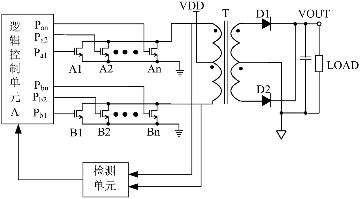
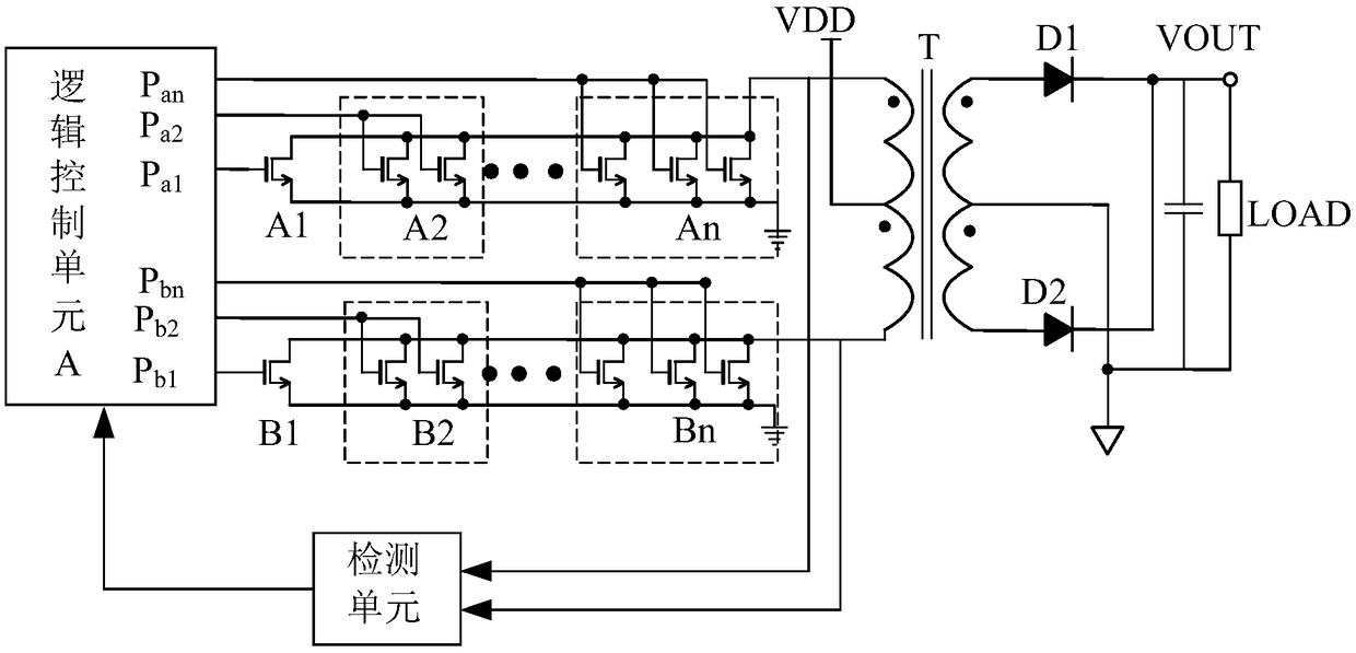
[0039] The embodiment of the present invention provides a push-pull converter circuit and a control method thereof, which solves the technical problem that the switch tube current is too large to cause damage to the push-pull converter circuit.

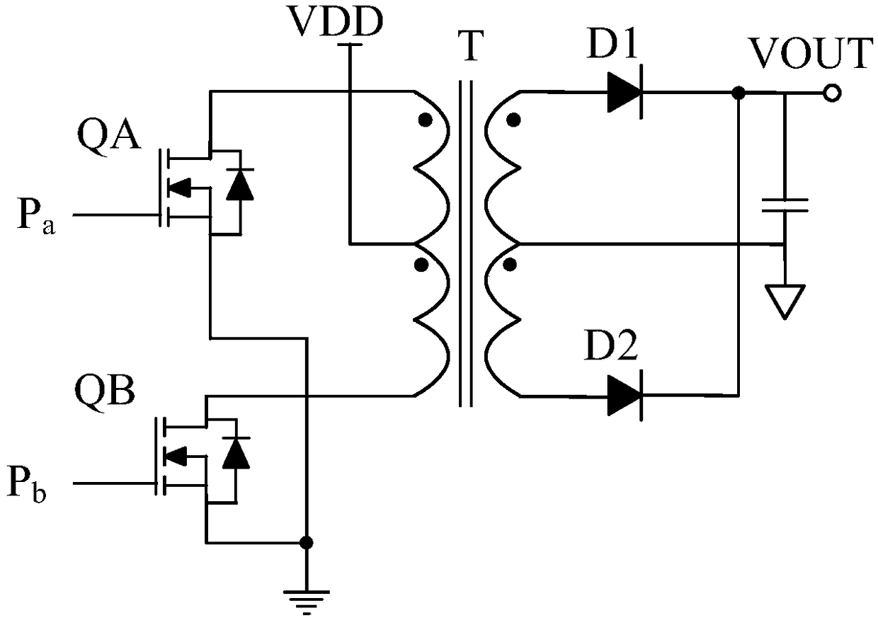
[0040] The inventor found in the research that because the existing push-pull converter circuit has only two switch tubes, and the two switch tubes are turned on alternately, when the output is over-current or short-circuited, the switch tube in the on-state will experience excessive current In order to avoid damage to the circuit of the push-pull converter, the switch tube in the over-current state can only be turned off after the over-current is detected. After the push-pull converter is turned off, there is no or only a small output power, resulting in output voltage Rapid drop, after the output overcurrent or short circuit fault is removed, the output capacitor needs to be charged to build up the output voltage, but because the cap...


PUM


Abstract

The invention discloses a push-pull converter circuit and a control method thereof. Equivalent parameters of two switch tube groups are same, each switch tube group comprises multiple stages of switchtubes in parallel, each stage of switch tube comprises one or more switch tubes in parallel, a logic control unit is connected with control ends of all switch tubes in the two switch tube groups andis used for performing push-pull driving control on the two switch tube groups according to a multi-path driving control signal, one path of driving control signal is used for independently controlling one stage of switch tubes, a detection unit is connected with the two switch tube groups and is used for detecting whether each switch tube group is in an overcurrent state or not, and when the switch tube groups are in the overcurrent states, the logic control unit is used for switching off at least one stage of switch tubes in the switch tube group so that the switch tube groups are in current-limiting states. By the push-pull converter circuit, the technical problem of damage to the push-pull converter circuit caused by excessively large current of the switch tubes is solved.

Description

technical field [0001] The invention relates to the field of circuit technology, in particular to a push-pull converter circuit and a control method thereof. Background technique [0002] The circuit structure of the push-pull converter is simple, the transformer is bidirectionally excited during operation, the utilization rate of the magnetic core is high, and it has the advantages of small size, high efficiency and good dynamic response. It needs electrical isolation in low voltage input, high current output and input and output occasions are widely used. [0003] There are various circuit structures of existing push-pull converters, figure 1 The push-pull converter circuit shown is one such configuration. Although there are many kinds of existing push-pull converter circuit structures, all of them can be divided into three parts: transformer primary circuit, transformer and transformer secondary circuit. To supply power to the load in the secondary circuit of the trans...

Claims


Application Information

Patent Timeline
Patent Type & Authority Applications(China)
IPC IPC(8): H02M3/337H02M1/32
CPCH02M1/32H02M3/3378H02M1/0009
Inventor 周立功翁粤冠
Owner GUANGZHOU ZHIYUAN ELECTRONICS CO LTD
Why Eureka
Try Eureka