Photovoltaic module heat collection device

A technology for photovoltaic modules and heat collection devices, applied in the field of photovoltaics, can solve the problems of low heat transfer efficiency, affecting photovoltaic power generation efficiency and heat collection efficiency, etc., and achieve the effects of large heat exchange area, good heat insulation, and increased heating time.

Inactive Publication Date: 2018-11-30
SICHUAN SHUANGLV TECH CO LTD
View PDF0 Cites 0 Cited by
  • Summary
  • Abstract
  • Description
  • Claims
  • Application Information

AI Technical Summary

Problems solved by technology

[0007] The technical problem to be solved by the present invention is: the heat transfer medium of the heat collection structure of the existing photovoltaic module has low heat transfer efficiency during the heat transfer process, which affects the photovoltaic power generation efficiency and heat collection efficiency

Method used


Image

  • Photovoltaic module heat collection device
  • Photovoltaic module heat collection device

Examples


Embodiment 1

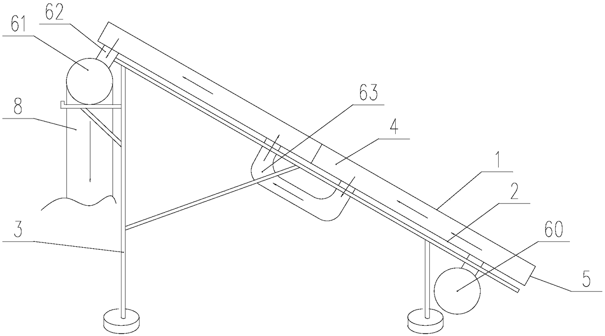
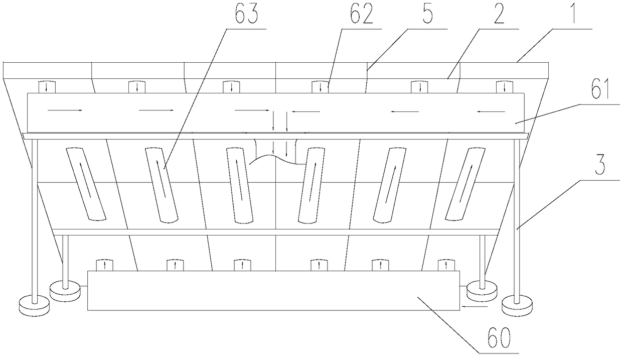
[0029] Such as figure 1 and figure 2 As shown, a photovoltaic module heat collecting device 1 includes a photovoltaic module 1, a heat collecting plate 2 and a supporting frame 3, and the photovoltaic module 1 and the heat collecting plate 2 are installed on the supporting frame 3, and the heat collecting plate 2 is connected to the heat conducting frame 5 of the photovoltaic module 1, the heat collecting plate 2, the heat conducting frame 5 and the back of the photovoltaic module 1 are surrounded to form a hollow heat exchange space 4, and the ventilation pipe 6 is connected to the heat collecting The back of the plate 2 is in communication with the heat exchange space 4, and the photovoltaic module 1 is composed of 8 single solar cells in 2 series and 6 in parallel.

[0030] Further, the material used for the heat conduction frame 5 is aluminum, and the material used for the heat collecting plate 2 is an aluminum-plastic plate.

[0031] Further, the heat collecting plate ...

Embodiment 2

[0034] The difference between this embodiment and Embodiment 1 is that the photovoltaic module 1 and the heat collecting plate 2 are obliquely installed on the support frame 3, and the ventilation duct 6 includes a The lower ventilation pipe 60 of the air inlet and the upper ventilation pipe 61 with an air outlet arranged on the inclined upper end of the heat collecting plate 2, the upper ventilation pipe 61 and the lower ventilation pipe 60 communicate with each other. After entering the inlet, the hot air will move upwards after being subjected to the backplane of the photovoltaic module 1 and the heat transfer temperature rise. Therefore, the hot air will move from the lower end to the upper end along the heat exchange space 4, and the push of the external air will accelerate the process. Movement, so that the air flowing in the heat exchange space 4 will quickly take away the heat on the back of the photovoltaic module 1 and the heat collecting plate 2, so that the heat dis...


PUM


Abstract

The invention discloses a photovoltaic module heat collection device, and solves the problems that the heat transfer efficiency of a heat transfer medium in a heat collection structure of the existingphotovoltaic module is low in the heat transfer process, and the photovoltaic power generation efficiency and heat collection efficiency are influenced. The photovoltaic module heat collection devicecomprises a photovoltaic module, a heat collecting plate and a supporting frame, wherein the photovoltaic module and the heat collecting plate are arranged on the supporting frame; the heat collecting plate is connected with a heat conduction frame of the photovoltaic module; the heat collecting plate, and the heat conduction frame and the back face of the photovoltaic module are enclosed to forma hollow heat exchange space; and a ventilating pipeline is connected to the back face of the heat collecting plate and is communicated with the heat exchange space. The photovoltaic module heat collection device has the advantages of being rapid in heat exchange, high in heat collection, high in power generation efficiency of the photovoltaic module and the like.

Description

technical field [0001] The invention relates to the field of photovoltaic technology, in particular to a heat collecting device for a photovoltaic module. Background technique [0002] A single solar cell cannot be directly used as a power source. As a power supply, a number of single cells must be connected in series, parallel and tightly packed into a photovoltaic module. Photovoltaic modules (also called solar panels) are the core components and the most important part of solar power generation systems. Its function is to convert the solar energy into electrical energy, and store it in the battery or push the load to work. [0003] At present, there are two main ways to apply solar energy, one is photovoltaic power generation, and the other is solar thermal utilization. The efficiency of photovoltaic power generation is relatively low, only about 20%, and most of the remaining energy exists in the form of heat energy. The high-temperature heat energy accumulated on th...

Claims


Application Information

Patent Timeline
IPC IPC(8): H02S40/42H02S20/10F24S25/61
CPCH02S20/10H02S40/42Y02E10/50
Inventor 陈骏
Owner SICHUAN SHUANGLV TECH CO LTD
Why Eureka
Try Eureka