
High-efficiency multi-layer electrostatic precipitator

An electrostatic precipitator and high-efficiency technology, which is applied in electrostatic separation, electrostatic effect separation, electrode structure and other directions, can solve the problems of affecting the dust removal effect of electrostatic precipitators, the inability to collect by the collecting plate, and increasing the burden of land use, so as to improve the electrostatic precipitator effect, Small footprint and improved charge rate

Inactive Publication Date: 2018-12-04
GUILIN YUXIN AGRI TECH CO LTD
View PDF0 Cites 1 Cited by
  • Summary
  • Abstract
  • Description
  • Claims
  • Application Information

AI Technical Summary

Problems solved by technology

[0002] Dust collectors are widely used in chemical industry, coal mine and other fields. Existing dust collectors mainly include cloth bags and electrostatic precipitators. Among them, electrostatic precipitators conduct adsorption and collection through collecting plates with opposite polarities after charging the dust. However, the waste gas The dust content in the medium is extremely large, and a large amount of dust is often not charged through a single charge, so that the subsequent collecting plate cannot effectively collect it, which greatly affects the dust removal effect of the current electrostatic precipitator; moreover, The current electrostatic precipitator is a single air duct, so its volume is often relatively large, which increases the land use burden for small places

Method used


Image

  • High-efficiency multi-layer electrostatic precipitator

Examples


Embodiment Construction

[0011] The technical solution of this patent will be described in further detail below in conjunction with specific embodiments.

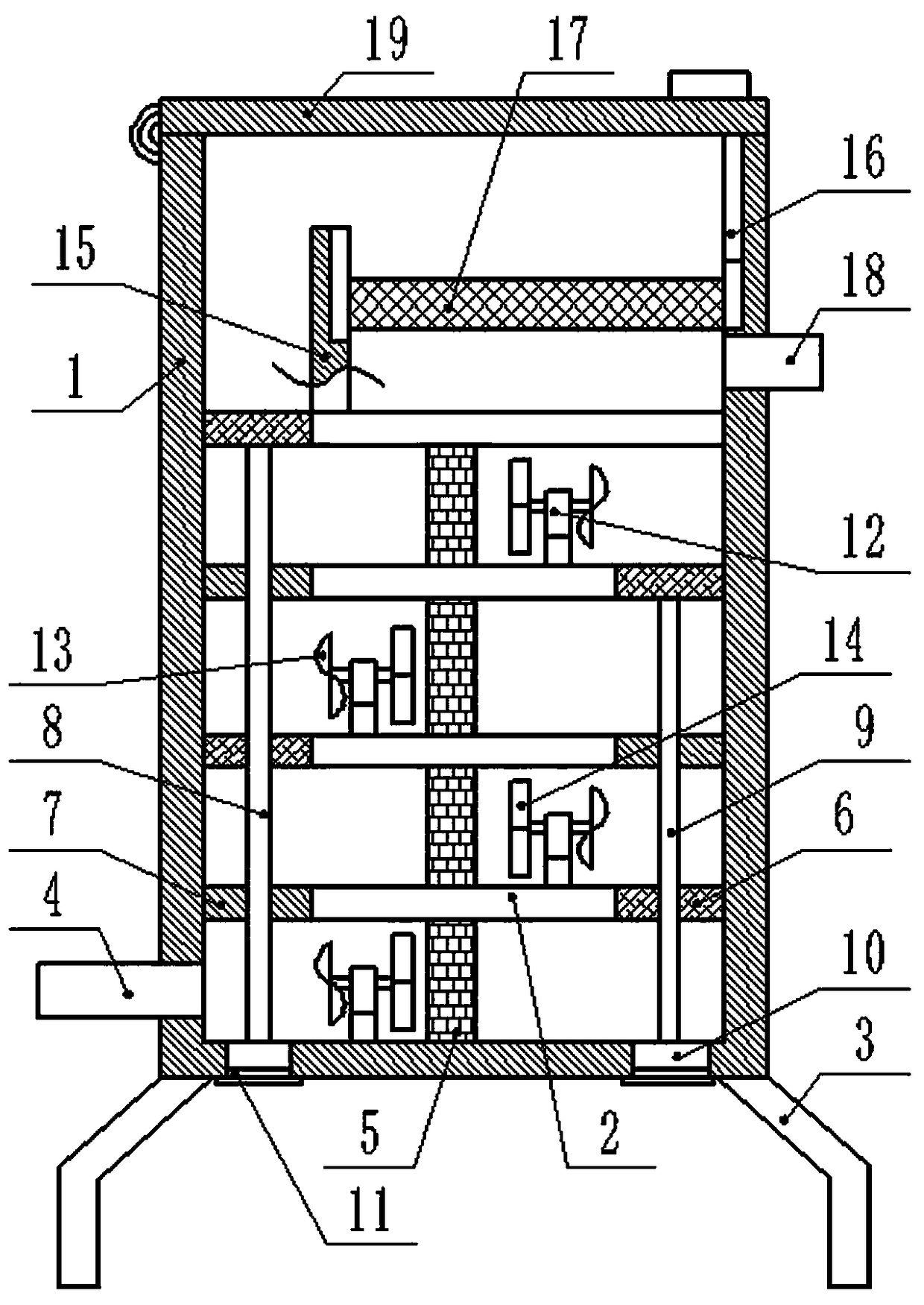
[0012] See figure 1 , A high-efficiency multilayer electrostatic precipitator, comprising a box body 1 and a partition plate 2, the lower end of the box body 1 is fixedly connected with a number of feet 3, the lower end of the left side of the box body 1 is connected with an air inlet pipe 4, the partition The plate 2 is provided with a plurality of equidistant and even fixed connections in the box body 1. The electrode mesh plate 5 is fixedly connected between the lower end of the partition plate 2 and the lower partition plate 2 and the bottom plate of the box body 1. There is an opening on the left side of the upper partition plate 2, and the other partition plates 2 have openings on both sides. The electrode dust collecting net 6 and the baffle 7 are tightly connected in the openings through sealing gaskets, and the electrode dust collecting nets ...


PUM


Abstract

The invention discloses a high-efficiency multi-layer electrostatic precipitator, comprising a box body and division plates, wherein a plurality of the division plates are equidistantly and uniformlyarranged in and fixedly connected with the box body; the lower ends of the division plates are fixedly connected with an electrode screen plate; two ends of the division plates are respectively and tightly connected with electrode dust-collecting nets and baffle plates; the electrode dust-collecting nets and the baffle plates located at left and right sides are separately connected with a long through pipe and a short through pipe; the lower ends of the long through pipe and the short through pipe are respectively connected with a blocking and pulling plate; the bottom plate of the box body and the division plates are fixedly connected with flow-disturbing racks symmetrically arranged at intervals; the flow-disturbing racks are rotatably connected with rotating shafts; two ends of the rotating shafts are respectively in interference fitting with slant-surface wind wheels and straight-surface impellers; the uppermost division plate is fixedly connected with a stabilizing frame; the right side wall of the stabilizing frame and the right inner wall of the box body are respectively provided with an open chute; and dust collecting net bags are slidably arranged in and connected with theopen chutes. The high-efficiency multi-layer electrostatic precipitator of the invention is good in dedusting effect, small in occupied land area and easy to maintain, and greatly improves the practicality of existing dust collectors.

Description

Technical field [0001] The invention relates to a chemical dust removal equipment, in particular to a high-efficiency multilayer electrostatic precipitator. Background technique [0002] Dust collectors are widely used in the chemical industry, coal mines and other fields. Existing dust collectors mainly include bag, electrostatic and other types. Among them, electrostatic precipitators collect the dust through the collection plate with opposite polarity after charging, but the exhaust gas The medium dust content is extremely large, and a large amount of dust is often uncharged through a single primary charge addition, so that subsequent collection plates cannot effectively collect it, which greatly affects the dust removal effect of current electrostatic precipitators; moreover, The current electrostatic precipitators are all single air ducts, so their volume is often relatively large, which increases the burden of land for small places. Summary of the invention [0003] The obj...

Claims


Application Information

Patent Timeline
Patent Type & Authority Applications(China)
IPC IPC(8): B03C3/017B03C3/36B03C3/40B03C3/34
CPCB03C3/017B03C3/34B03C3/368B03C3/40
Inventor 朱文胜
Owner GUILIN YUXIN AGRI TECH CO LTD
Learn More