Novel fuel cells and methods of manufacturing the same

a fuel cell and fuel technology, applied in the field of fuel cells, can solve the problems of high fuel efficiencies, high cost of membrane materials and catalysts, and high cost of solid oxide fuel cells, and achieve the effects of increasing reaction efficiency, increasing efficiency, and increasing the rate of charged particles (oxygen ions) transport across the solid oxide electroly

Inactive Publication Date: 2008-01-03
APPLIEDUS CORP
View PDF12 Cites 21 Cited by
  • Summary
  • Abstract
  • Description
  • Claims
  • Application Information

AI Technical Summary

Benefits of technology

[0039]To manufacture solid oxide fuel cell (SOFC) electrolyte at lower temperatures, metal of the oxide membrane, for example zirconium metal in the zirconium oxide membrane, is used to construct the solid membrane structure from zirconium metal at a lower manufacturing temperature, and the metal is then oxidized to form zirconium oxide to impart the electrolyte characteristics. Adjusting the fraction of the excess metal remaining, after oxidation of zirconium, may then control defect concentration of zirconium oxide. In this way the rate of charged particle (oxygen ion) transport across the solid oxide electrolyte can be increased.
[0040]For increased reaction efficiencies, the novel three-dimensional fuel cell design provides a stack of rows of closely spaced electrodes / channels, each set of electrode / channel rows, alternately carrying fuel gas and oxygen containing gas; electrodes within hydrogen and oxygen carrying channels being connected to form two separate electrode systems; and, all within a matrix of electrolyte material, which is a continuous medium produced in dimensions sufficient to create desired electrical energy; said medium may also act as load carrying fuel cell construction material. Electrolyte material can be any conventionally used electrolyte material, can have short-circuit pores for increased efficiency; or solid oxide electrolyte first manufactured by using the metallic element and later oxidized to create the oxide electrolyte.
[0041]Because the transport rates of charged particles across the electrolyte can be increased significantly, initial minimum operational temperature of the fuel cells of this invention can be lower than the conventional fuel cells. Since the electrolyte “membrane” thickness, or its effective thickness, as well as fuel and oxygen carrying channel dimensions are reduced significantly, reaction surface area per unit volume of cell is increased many fold. This then increases the efficiency of reactions producing energy, and significantly reduces the fuel cell volume.
[0042]Thus, this invention offers long lasting fuel cells potentially hundreds of times more powerful than any of the existing fuel cells, at lower prices, and with more reliability.

Problems solved by technology

There are a number of barriers to their wider use.
The main issue is cost as the membrane materials and catalysts are expensive, and also they need pure hydrogen to operate, as they are very susceptible to poisoning by carbon monoxide and other impurities.
AFC power density is about ten times lower than that of a PEM cell so they are too bulky for use in car engines.
Solid oxide fuel cells, though have high fuel efficiencies, are expensive because of the cost of materials that must withstand high temperatures and thermal cycling.
Regardless of the type, the biggest drawback for commercialization of existing fuel cells is their high cost.
1. low reaction surface area per unit volume,
2. high materials cost, partly due to their frequent failure under cyclic thermal loading and / or corrosive environment, and
3. the very thin electrolytes, electrodes, and flow plates are too difficult to manufacture.
In the process of putting the three flat pieces together membrane frequently gets damaged, and loses its functional character.
To this assembly, a pair of field flow plates to carry the gasses are attached, again requiring a separate manufacturing step, and exposing the assembly to manufacturing induced defects, and increasing manufacturing cost.
Presently, electrolyte membranes for the Solid Oxide Fuel Cells (SOFC) are manufactured by sintering or by hot pressing at very high temperatures, which increase the manufacturing cost.

Method used


Image

  • Novel fuel cells and methods of manufacturing the same
  • Novel fuel cells and methods of manufacturing the same
  • Novel fuel cells and methods of manufacturing the same

Examples


Embodiment Construction

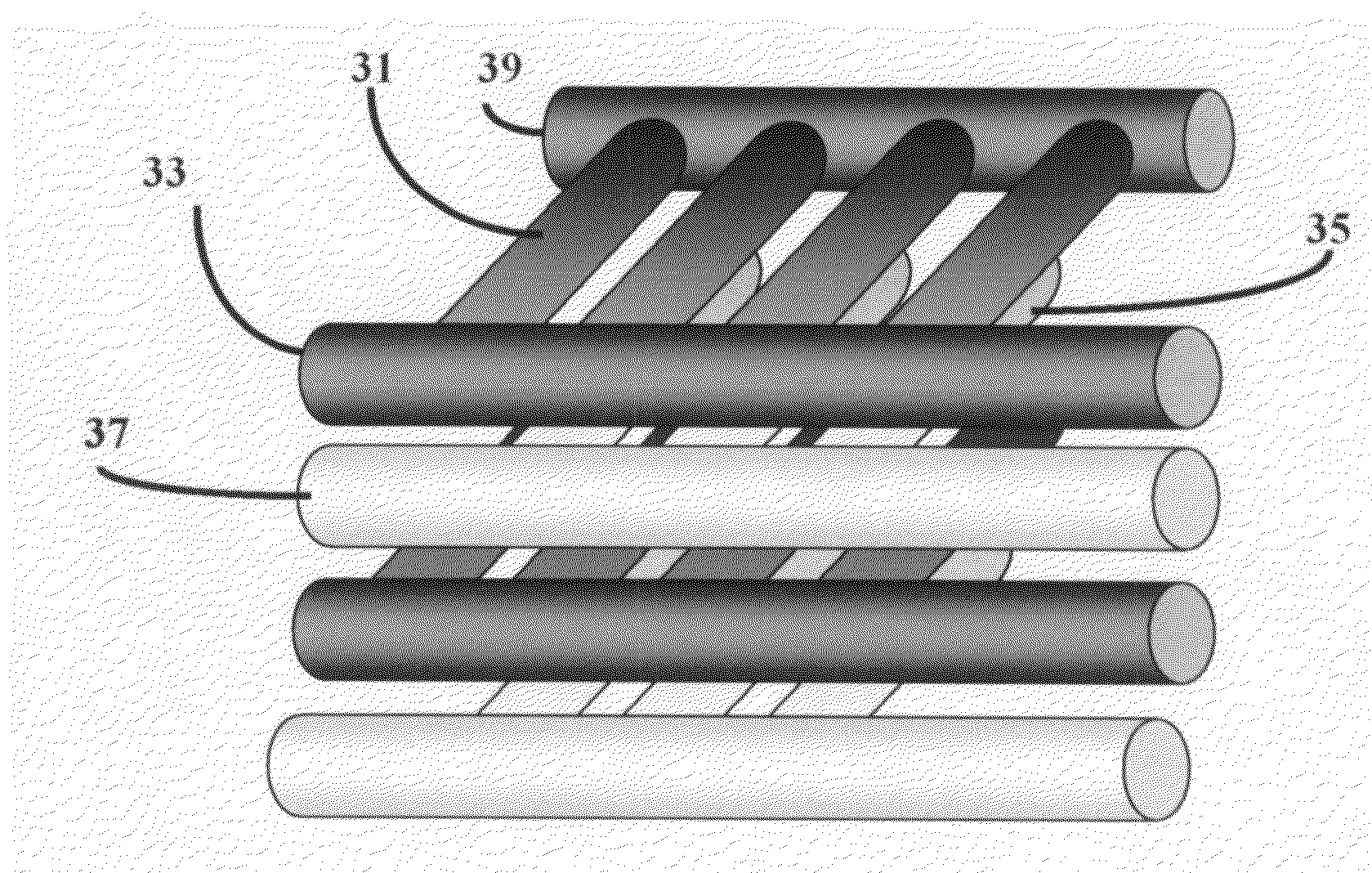
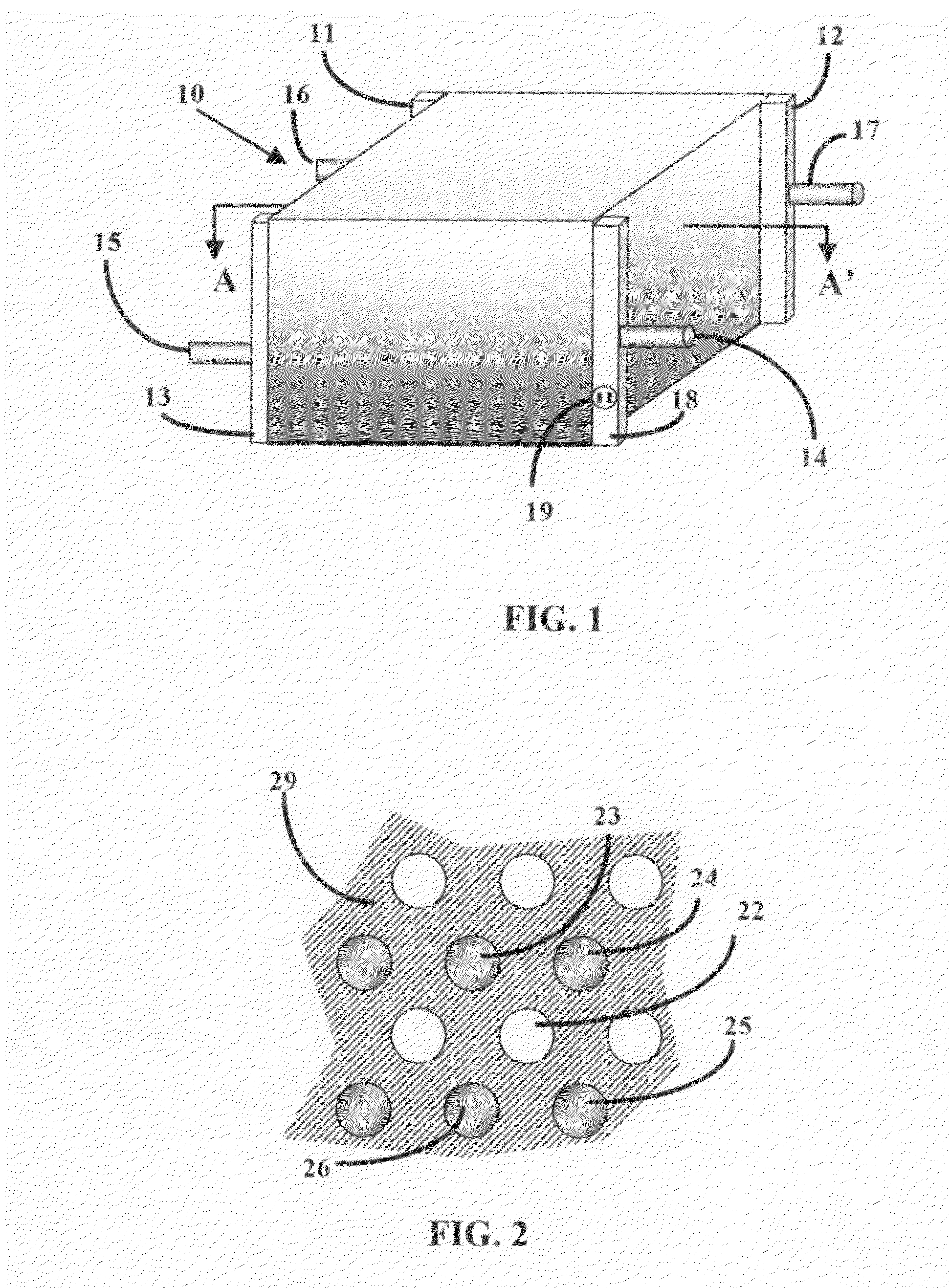
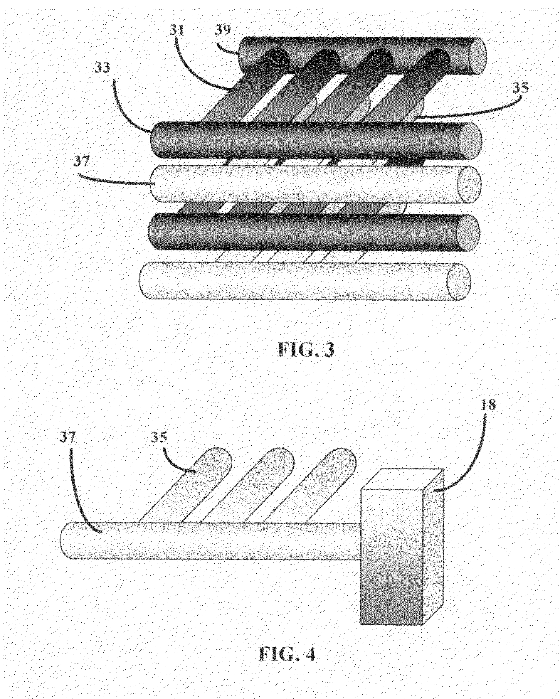
[0058]A fuel cell is a device that uses hydrogen (or hydrogen-rich fuel) and oxygen to create electricity. Components of a single fuel cell include two electrodes, which act as porous anode and cathode, each with or without a coating of a catalyst. The need for a catalyst is reduced with increasing reaction temperature. Between the two electrodes there is an electrolyte, through which either protons move toward cathode where they combine with oxygen ions, or negative ions (anions), formed at the cathode travel toward the anode where they combine with hydrogen to generate water and electrons.

[0059]Electrolyte is the key material, as it allows ions to travel through it, but does not permit electrons. Electrons generated from hydrogen molecules travel through a circuit providing external energy. Electrons, in PEFC and PAFC type fuel cells, are generated at the anode along with protons from hydrogen, and return to the cathode completing the circuit. For AFC, MCFC, and SOFC types electro...


PUM

PropertyMeasurementUnit
temperatureaaaaaaaaaa
temperaturesaaaaaaaaaa
volumeaaaaaaaaaa

Abstract

A fuel cell, comprising an electrolyte body and, embedded within it, at least two separate electrodes capable of conducting electrons; the electrodes being sufficiently porous to allow gas flow through them; one electrode being an electrically negative anode and the other electrode being an electrically positive cathode, and the electrolyte body being capable of carrying charged particles between the anode and cathode; the anode and cathode being electrically connected to form an electrical circuit.

Description

[0001]The present invention claims priority to U.S. Provisional Patent Application No. 60 / 818,401, filed Jul. 3, 2006, and U.S. provisional Patent Application No. 60 / 875,102, filed Dec. 16, 2006, each of which are specifically herein incorporated by reference in their entirety.BACKGROUND OF THE INVENTION[0002]The present invention is directed towards fuel cells. More specifically, the invention is a type of fuel cell wherein the ionic conduction medium is also the body of the cell. In one embodiment, ionic conduction medium is created by a chemical reaction while the fuel cell is manufactured. The manufacturing process, used to create the cell body, can also manufacture the electrodes, fuel and oxidant gas transmission lines, and if necessary, place catalysts in proper locations within the cell.BACKGROUND AND PRIOR ART[0003]Fuel cells generate electricity from a reaction between oxygen and hydrogen. Several different types of fuel cell that exist presently are all based around a cen...

Claims


Application Information

Patent Timeline
Patent Type & Authority Applications(United States)
IPC IPC(8): H01M8/10H01M6/18H01M8/08
CPCH01M4/8605H01M8/0291H01M8/08H01M8/1004Y10T29/49108H01M2008/1293Y02E60/521Y02E60/525H01M2008/1095H01M8/0289Y02E60/50Y02P70/50
Inventor ECER, GUNES M.
Owner APPLIEDUS CORP
Why Eureka
Try Eureka