Printing equipment with buffering function

A technology of printing equipment and functions, which is applied in the field of printing equipment, can solve the problems of inability to absorb vibration of printing rollers, inability to lift, low application range, etc., and achieve the effect of increasing the application range, improving the conveying effect, and improving the printing effect

Inactive Publication Date: 2018-12-04
张家港市杨舍丝印工艺厂
View PDF0 Cites 0 Cited by
  • Summary
  • Abstract
  • Description
  • Claims
  • Application Information

AI Technical Summary

Problems solved by technology

[0003] Existing printing equipment is usually a fixed structure that cannot be raised and lowered, resulting in that the printing equipment can only print on paper of one thickness, which reduces the printing range, and at the same time cannot dampen the printing roller. When the equipment transports the paper, it usually needs to sort the paper manually, which increases the workload of the personnel and has a low scope of application.

Method used


Image

  • Printing equipment with buffering function
  • Printing equipment with buffering function
  • Printing equipment with buffering function

Examples


Embodiment Construction

[0022] In order to make the technical means, creative features, goals and effects achieved by the present invention easy to understand, the present invention will be further described below in conjunction with specific embodiments.

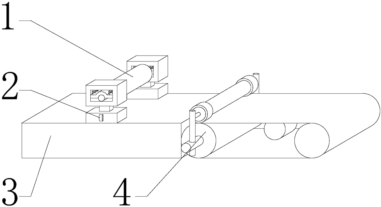
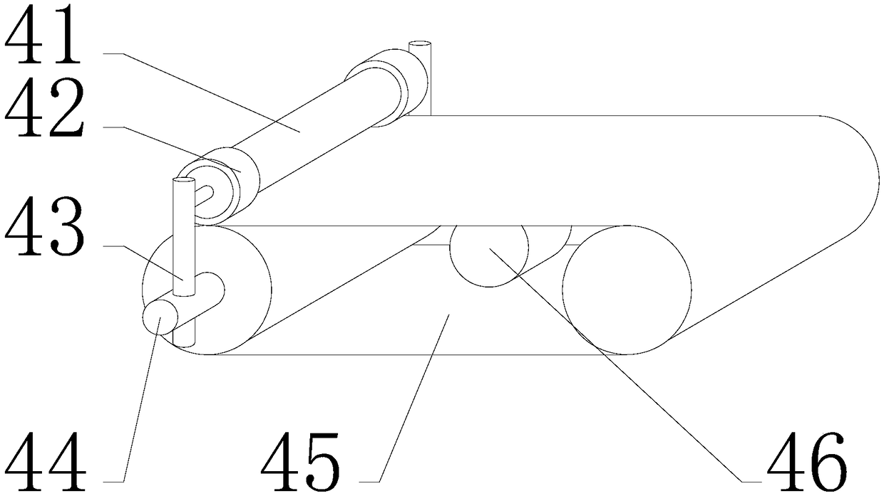
[0023] see Figure 1-Figure 3 , the present invention provides a technical solution: a printing device with a buffer function, including a printing roller 1, a supporting mechanism 2, a device main body 3 and a conveying mechanism 4, the outer end of the printing roller 1 is installed with a supporting mechanism 2, and the supporting mechanism 2 is assembled on On the upper end of the equipment main body 3, a printing roller 1 is arranged on the upper side of the equipment main body 3, and the right end of the equipment main body 3 is connected to the conveying mechanism 4.

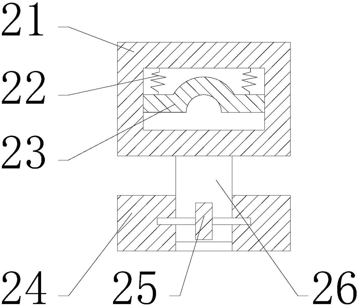
[0024] The support mechanism 2 includes a support frame 21, a spring 22, an arc-shaped pressing plate 23, a support block 24, a circular gear 25, and a rack 26. The spring 22...


PUM


Abstract

The invention provides printing equipment with a buffering function. The printing equipment comprises a supporting frame, springs, an arc-shaped pressing plate, a supporting block, a circular gear, arack, a rolling shaft, limiting rings, guide rods, supporting rods and a conveying belt, wherein the springs are installed at the top end inside the supporting frame, the lower end of each spring is connected with the arc-shaped pressing plate, the rack is installed at the lower end of the supporting frame, the supporting block is arranged at the lower end of the rack, the circular gear is inlaidat the front end of the supporting block, the circular gear is in gear meshing with the rack, the limiting rings are installed on the rolling shaft, and the guide rods are arranged at the outer ends of the rolling shaft. The guide rods comprise an outer rod with a hollow structure and two inner rods which are respectively inserted into the two ends of the outer rod, one inner rod can stretch and be fixed in the axial direction of the outer rod, and the other inner rod stretches and is clamped in the axial direction of the outer rod through a spiral mechanism; and each inner rod is provided with a clamping mechanism, each supporting rod is installed at the lower end of the corresponding guide rod, and the conveying belt is assembled at the inner ends of the supporting rods. According to theprinting equipment, position limitation can be conducted, the printing equipment can be lifted and automatically limited, the stability is good, and the reliability is high.

Description

technical field [0001] The invention is a printing device with a buffer function, which belongs to the field of printing devices. Background technique [0002] Printing equipment is a machine that processes and finishes printed sheets into printed products. There are three methods of binding books and periodicals: wire binding, paperback and hardcover. Generally, it goes through the processes of cutting, folding, collating, book block processing, book stapling, wrapping, book cutting, and packaging. [0003] Existing printing equipment is usually a fixed structure that cannot be raised and lowered, resulting in that the printing equipment can only print on paper of one thickness, which reduces the printing range, and at the same time cannot dampen the printing roller. When the equipment transports the paper, it usually needs to sort the paper manually, which increases the workload of the personnel and has a low scope of application. Contents of the invention [0004] In...

Claims


Application Information

Patent Timeline
IPC IPC(8): B41F13/20B41F13/34B65H5/22
CPCB41F13/20B41F13/34B65H5/224
Inventor 戴积法戴强王诚
Owner 张家港市杨舍丝印工艺厂
Why Eureka
Try Eureka