Automatic fuel particle moulding and processing device
A fuel particle and automatic processing technology, applied in the direction of biofuel, waste fuel, fuel, etc., can solve problems such as machine jamming, achieve the effects of reducing costs, improving work efficiency, and preventing overload
- Summary
- Abstract
- Description
- Claims
- Application Information
AI Technical Summary
Problems solved by technology
Method used
Image

Examples
specific Embodiment approach 1
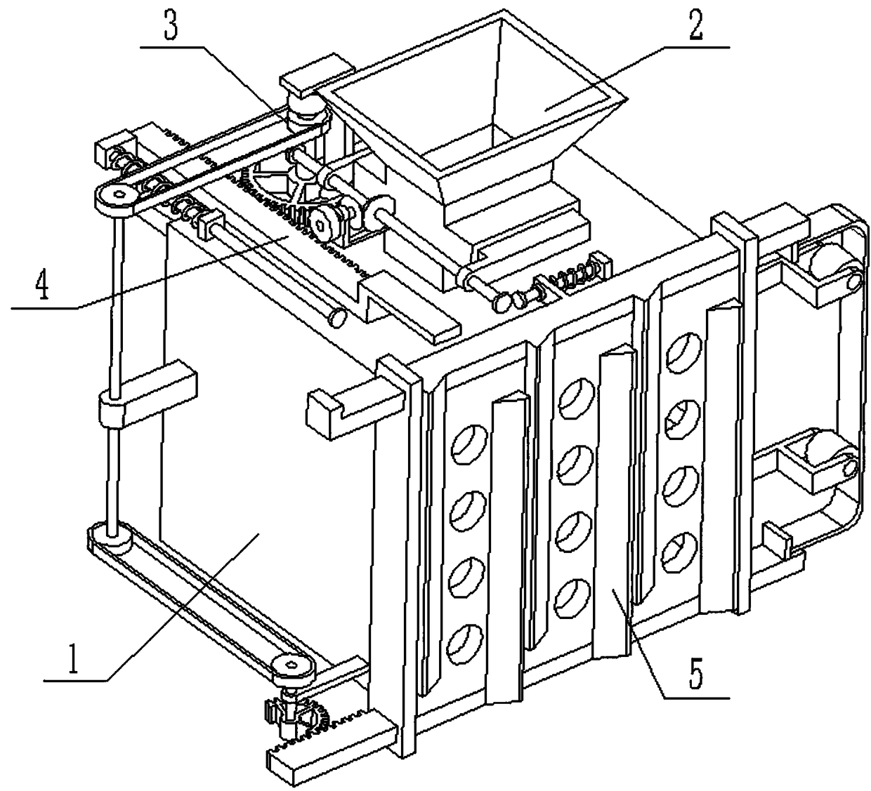
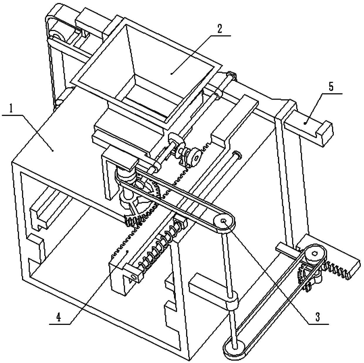
[0026] Combine below Figure 1-8 Describe this embodiment, an automatic processing device for forming material fuel particles, including a fuel extrusion box 1, an intermittent feeding seat 2, a power driver 3, a material extruding plate 4 and a cutting knife 5, the intermittent feeding seat 2 Set on the upper end of the fuel extrusion box 1, the intermittent feeding seat 2 communicates with the interior of the fuel extrusion box 1, the power drive part 3 is arranged on the fuel extrusion box 1, and the extruding plate 4 is arranged on the fuel extrusion box 1 , the power driver 3 is in transmission connection with the extruding plate 4 , the cutting knife 5 is arranged at the front end of the fuel extrusion box 1 , and the power driver 3 is in transmission connection with the cutting knife 5 . When the present invention is in use, the material falls into the intermittent feeding seat 2. At this time, the intermittent feeding seat 2 is in a closed state, and the power driving ...
specific Embodiment approach 2
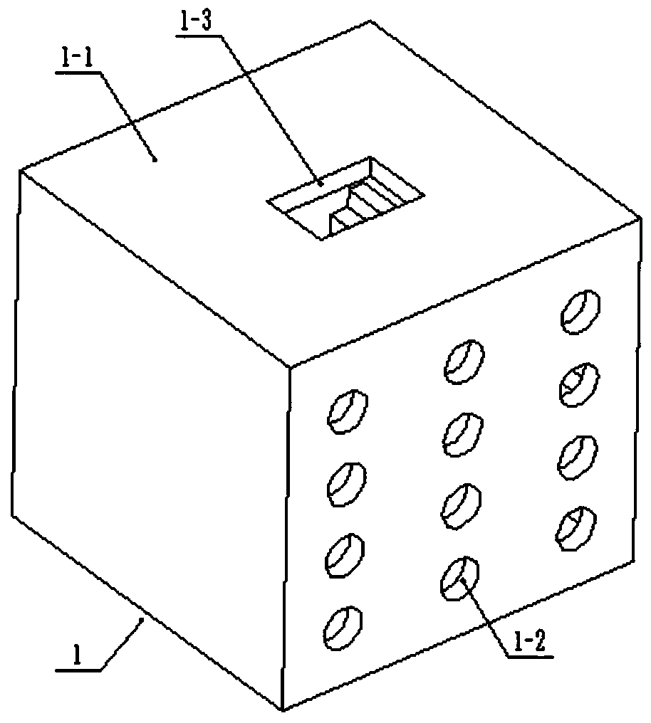
[0027] Combine below Figure 1-8 To illustrate this embodiment, the fuel extrusion box 1 includes a box body 1-1, four fuel forming holes 1-2 distributed longitudinally, a feed port 1-3, a T-shaped slide rail 1-4 and a stopper 1 -5; the rear end of the box body 1-1 is hollowed out, and the front end of the box body 1-1 is provided with three rows of longitudinally distributed fuel forming holes 1-2, and the upper end of the box body 1-1 is provided with a feed port 1-3, and the box body 1-1 T-shaped slide rails 1-4 are fixedly connected to the left and right end faces of the inner side of the body 1-1, and two stoppers 1-5 are fixedly connected symmetrically to the rear end of the box body 1-1.
[0028]The intermittent feeding seat 2 includes a feeding seat 2-1, a sliding sleeve 2-2, a material baffle 2-3, a two-way threaded rod 2-4, a driven bevel gear 2-5, a driving bevel gear 2-6, Feed control shaft 2-7, axle frame plate 2-8 and feed control gear 2-9; Feeding seat 2-1 is f...
specific Embodiment approach 3
[0030] Combine below Figure 1-8 To illustrate this embodiment, the power drive member 3 includes a motor frame 3-1, a motor 3-2, a driving pulley 3-3, an incomplete gear I 3-4, a driven pulley 3-5, and a drive shaft 3- 6. Shaft seat 3-7, drive pulley 3-8, drive pulley 3-9, drive shaft 3-10, horizontal frame plate 3-11 and incomplete gear II 3-12; motor 3-2 passes through motor frame 3- 1 is fixedly connected to the box body 1-1, and the output shaft of the motor 3-2 is fixedly connected with the driving pulley 3-3 and the incomplete gear I 3-4, and the driving pulley 3-3 is connected with the driven pulley 3 through a belt -5, the driven pulley 3-5 is fixedly connected to the upper end of the drive shaft 3-6, the drive shaft 3-6 is rotatably connected to the shaft seat 3-7 through the bearing with seat, and the shaft seat 3-7 is fixedly connected to the box 1-1, the drive pulley 3-8 is fixedly connected to the lower end of the drive shaft 3-6, the drive pulley 3-8 is connect...
PUM
 Abstract
Description
Claims
Application Information
 - R&D
- Intellectual Property
- Life Sciences
- Materials
- Tech Scout
- Unparalleled Data Quality
- Higher Quality Content
- 60% Fewer Hallucinations
Browse by: Latest US Patents, China's latest patents, Technical Efficacy Thesaurus, Application Domain, Technology Topic, Popular Technical Reports.
© 2025 PatSnap. All rights reserved.Legal|Privacy policy|Modern Slavery Act Transparency Statement|Sitemap|About US| Contact US: help@patsnap.com