Hydrogen refueling station hydrogen energy source supply method and system

A supply system and hydrogen energy technology, applied in the field of hydrogen energy applications, can solve the problems of low transportation efficiency and large recycling residual pressure, and achieve the effects of improving transportation efficiency, reducing recycling residual pressure, and reducing recycling costs

Active Publication Date: 2018-12-04
浙江昊凡科技有限公司
View PDF9 Cites 6 Cited by
  • Summary
  • Abstract
  • Description
  • Claims
  • Application Information

AI Technical Summary

Problems solved by technology

[0004] The technical problem to be solved by the present invention is to provide a hydrogen energy supply method and system for a hydrogen refueling station to solve the problems of large recovery residual pressure and low transportation efficiency of hydrogen supply equipment in a hydrogen refueling station

Method used


Image

  • Hydrogen refueling station hydrogen energy source supply method and system
  • Hydrogen refueling station hydrogen energy source supply method and system

Examples


Embodiment 1

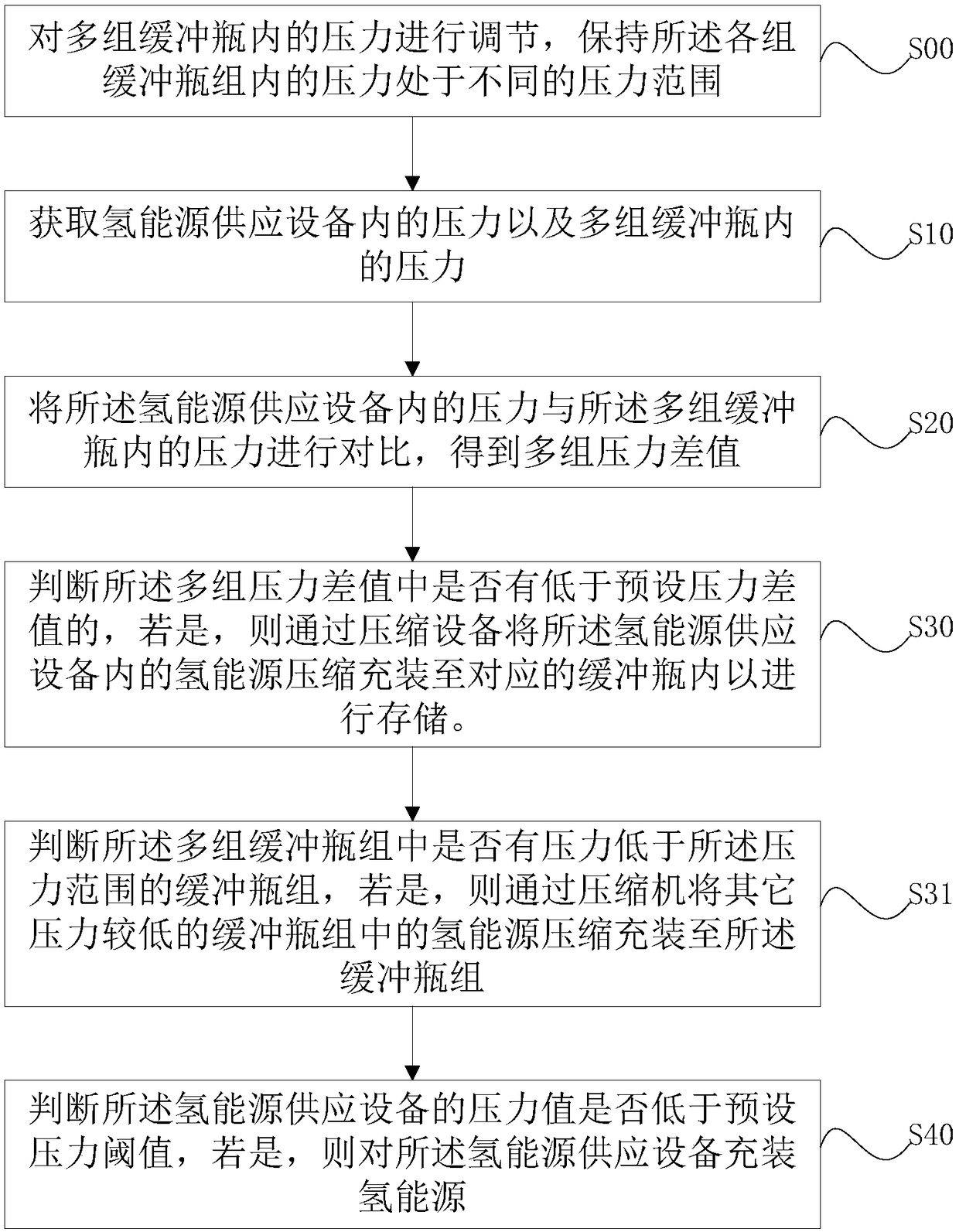
[0034] refer to figure 1 , this embodiment provides a hydrogen refueling station hydrogen energy supply method, including steps:

[0035] S10: Obtain the pressure in the hydrogen energy supply equipment and the pressure in multiple sets of buffer bottles;

[0036] S20: Comparing the pressure in the hydrogen energy supply equipment with the pressure in the multiple sets of buffer bottles to obtain multiple sets of pressure difference ratios;

[0037] S30: Determine whether any of the multiple sets of differential pressure ratios is lower than the preset differential pressure ratio, and if so, adjust the control logic of the compression equipment to compress and fill the hydrogen energy in the hydrogen energy supply equipment to the corresponding buffer bottle for storage.

[0038] In this embodiment, the hydrogen refueling station is equipped with a single-stage compressor and a buffer bottle for buffering hydrogen energy. The pressure capacity of the single-stage compressor ...

Embodiment 2

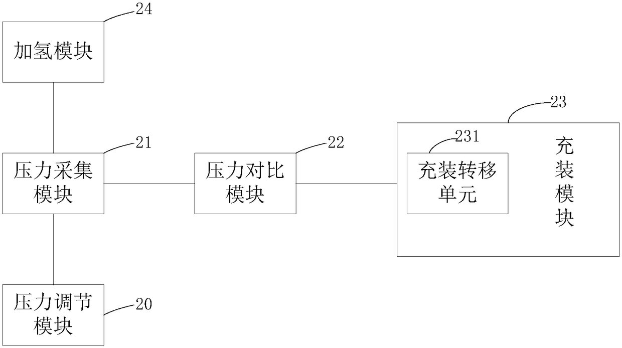
[0058] refer to figure 2 , this embodiment provides a hydrogen energy supply system for a hydrogen refueling station, including:

[0059] Pressure acquisition module 21: used to acquire the pressure in the hydrogen energy supply equipment and the pressure in multiple sets of buffer bottles;

[0060] Pressure comparison module 22: used to compare the pressure in the hydrogen energy supply equipment with the pressure in the multiple sets of buffer bottles to obtain multiple sets of pressure difference ratios;

[0061] Filling module 23: used to judge whether any of the multiple sets of differential pressure ratios is lower than the preset differential pressure ratio, and if so, compress and charge the hydrogen energy in the hydrogen energy supply equipment by adjusting the control logic of the compression equipment. Fill into corresponding buffer bottles for storage.


PUM


Abstract

The invention provides a hydrogen refueling station hydrogen energy source supply method, and a system. The hydrogen refueling station hydrogen energy source supply method and the system are used forsolving a problem in the prior art that hydrogen refueling station hydrogen energy source supply efficiency is low. The hydrogen refueling station hydrogen energy source supply method comprises following steps: S10, the pressure value in a hydrogen energy source supply equipment and the pressure values in a plurality of buffer bottles are obtained; S20, the pressure value in the hydrogen energy source supply equipment is compared with the pressure values in the plurality of buffer bottles so as to obtain a plurality of pressure difference values; S30, it is determined whether the pressure difference values are lower than a preset pressure different ratio, if a value from the pressure difference values is lower than the preset pressure difference ratio, control logic of a compression equipment is adjusted for compression and filling of hydrogen energy source in the hydrogen energy source supply equipment into a corresponding buffer bottle for storage. According to the hydrogen refuelingstation hydrogen energy source supply method, the plurality of buffer bottles with different pressure difference values are adopted, so that the recovery excess pressure of the hydrogen energy sourcesupply equipment can be reduced effectively, and supply efficiency and transportation efficiency can be increased.

Description

technical field [0001] The invention relates to the application field of hydrogen energy, in particular to a hydrogen energy supply method and system for a hydrogen refueling station. Background technique [0002] When hydrogen refueling stations provide hydrogen refilling for hydrogen energy vehicles and other equipment, due to the high cost of on-site hydrogen production and certain safety risks, most hydrogen refueling stations basically use tube bundle vehicles to transport and provide hydrogen sources, and then the tube bundles The hydrogen energy in the vehicle is compressed by the compressor and filled into the buffer bottle of the hydrogen refueling station to refuel the vehicle. The working pressure of the hydrogen storage bottle of the existing hydrogen energy car is 70MPa, and the working pressure of the hydrogen storage bottle of the bus or truck is 35MPa, and the compressor has a compression ratio limitation. For example, a compressor with a compression ratio of...

Claims


Application Information

Patent Timeline
Patent Type & Authority Applications(China)
IPC IPC(8): F17C5/06F17C13/00F17C13/02F17C13/04
CPCF17C5/06F17C13/00F17C13/002F17C13/026F17C13/04F17C2221/012F17C2265/063Y02E60/32Y02P90/45
Inventor 林培基陈艳程黎思锋
Owner 浙江昊凡科技有限公司
Why Eureka
Try Eureka