
A yield estimating method for a continuously produced coiled material

A production volume and yield technology, applied in the direction of optical testing defects/defects, etc., can solve the problems of reducing product quality, low accuracy of estimated yield, and reduced accuracy, so as to improve production quality, improve product yield, Accurate effect

Active Publication Date: 2018-12-04
SHENZHEN SAPO PHOTOELECTRIC
View PDF8 Cites 2 Cited by
  • Summary
  • Abstract
  • Description
  • Claims
  • Application Information

AI Technical Summary

Problems solved by technology

[0010] Low accuracy of estimated yield rate: The current yield rate estimation technology has the following problems that lead to inaccurate estimated yield rate: only relying on final part sampling and partial process inspection, without overall inspection and estimation of the entire roll; There is a big difference at the end of the middle roll, only the last part is sampled, the representativeness is not strong, and the sample size is small; the process yield estimation is based on manual inspection, and as the production speed increases, the difficulty of manual inspection increases and the accuracy decreases;
[0011] Cause product loss: each volume is sampled, and the sampled product cannot be used again, resulting in loss
[0012] There is a risk of reducing product quality: During process inspection, inspectors need to enter the clean room to inspect materials at close range (≤0.5m). Personnel are the largest source of pollution in the clean room, which will reduce the cleanliness and reduce product quality. risks of

Method used


Image

  • A yield estimating method for a continuously produced coiled material
  • A yield estimating method for a continuously produced coiled material
  • A yield estimating method for a continuously produced coiled material

Examples


Embodiment Construction

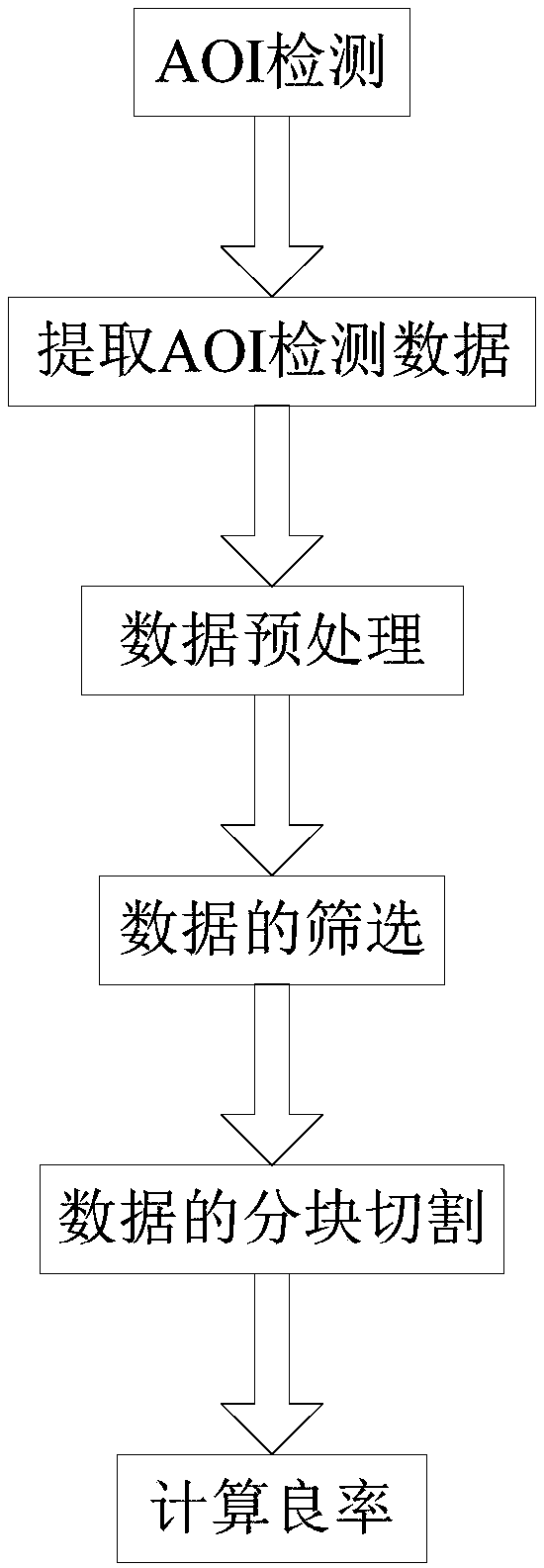
[0039] The present invention will be further described below in conjunction with the accompanying drawings.

[0040] Glossary:

[0041] AOI (Automatic Optic Inspector): automatic optical detector;

[0042] Md Pos (Machine direction Position): the position of the defect in the direction of film movement;

[0043] CdPos (Cross direction Position): the position of the defect in the vertical direction of film movement;

[0044] Class: the category of the defect;

[0045] Severity: the severity of the defect;

[0046] Slicing: After the production of the coil is completed, it needs to be matured for a period of time (7-10 days). After the mature, it needs to be cut into slices in a certain direction and size according to the requirements of the end customer;

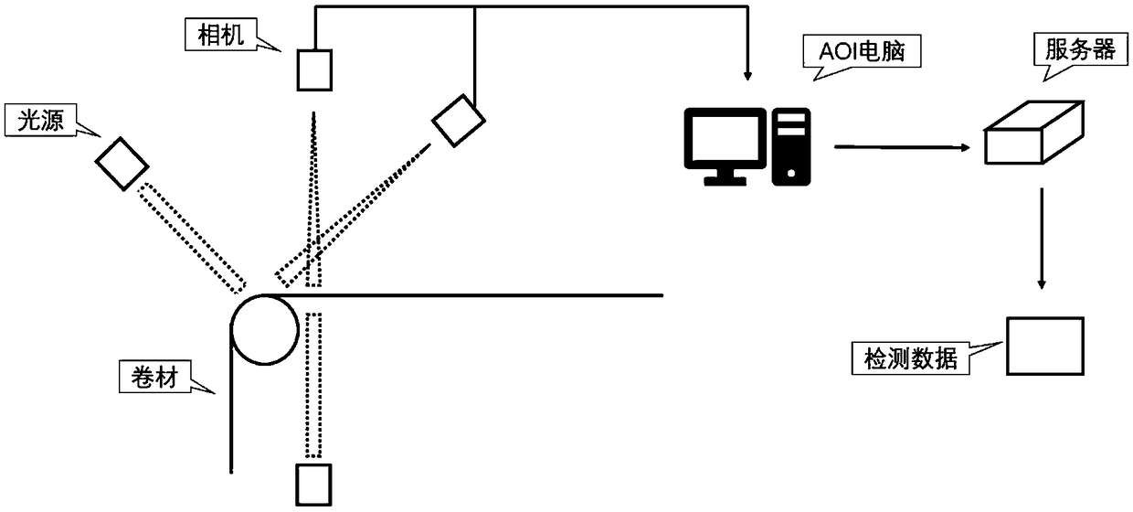
[0047] AOI is a device for real-time detection of defects encountered in coil production based on optical principles. It consists of imaging devices such as light sources, lenses, and CCDs, and back-end computer acquisiti...


PUM


Abstract

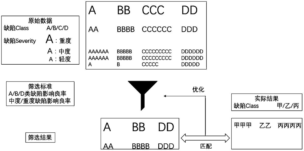
A yield estimating method for a continuously produced coiled material is provided. The method includes 1) a step of AOI detection, namely a step of performing non-contact real-time detection on each coil of the film material with an AOI device; 2) a step of AOI detection data extraction; 3) a step of data pretreatment, namely a step of unpacking the AOI detection data, and extracting data list heads to obtain needed defect information; 4) a step of data filtering; 5) a step of data section splitting, namely a step of, through a program, subjecting the coiled material to section splitting according to a section dimension and direction of an actual sheet-shaped finished product, and making a split diagram in one-to-one correspondence with an actual situation; and 6) a step of calculating thesplit diagram obtained in the step 5) to obtain an estimated yield high in accuracy. The estimated yield is high in accuracy and high in reliability, and is adopted as feedback data to improve the production quality and increase the product yield. The method has no influence on the yield of the coiled material through the non-contact detection, and sampling is not needed so that consumption is avoided.

Description

technical field [0001] The invention relates to a yield rate estimation method, in particular to a yield rate estimation method of roll materials. Background technique [0002] The roll length of roll-shaped materials is usually greater than 1000 meters, and the production is continuous without interruption, which is closely related to the production status. The quality of the rolls at the beginning and the end of rolls varies greatly; with the development of time, the production speed of roll-shaped materials has been greatly improved. [0003] For the current continuous production of roll materials, there may be no yield rate estimation during the production process; or there is only a simple yield rate estimation method, which consists of sampling inspection at the end of each roll and online process inspection, and only grades A / B / C / D, without a specific value, the estimated yield grade is the lowest grade between the final product grade and the process grade. [0004]...

Claims


Application Information

Patent Timeline
IPC IPC(8): G01N21/89
CPCG01N21/89
Inventor 田霖陈培灿杨维平陈雪弟范若琪
Owner SHENZHEN SAPO PHOTOELECTRIC
Learn More