Control method of programmable logic controller

A programming logic and control method technology, applied in the field of automatic control, can solve the problems of complex design process, difficult fault finding, high cost, etc., and achieve the effect of simple and intuitive programming, simple and intuitive configuration programming, and convenient fault finding

Active Publication Date: 2018-12-04
闫伟
View PDF6 Cites 3 Cited by
  • Summary
  • Abstract
  • Description
  • Claims
  • Application Information

AI Technical Summary

Problems solved by technology

[0005] 1. The design process is complicated: as mentioned above, the programmable logic controller currently used to realize circuit control needs to go through multiple departments and multiple design processes, and then the program is written by professional programmers, and finally downloaded to the system of the programmable logic controller , in order to realize the control of the equipment
[0006] 2. Expensive: In a centralized control automation project, the upper computer configuration equipment, programming equipment and lower computer control equipment have become necessary equipment, and the price of the two systems accounts for a considerable part of the cost of the entire project. proportion
[0007] 3. Difficulty in troubleshooting: For some large systems with many input and output points, if the equipment fails, the programming notes or the I / O table corresponding to the port are lost, it will cause considerable difficulties for maintenance personnel to troubleshoot. Skilled operation of automation program programming and configuration is a long process that requires long-term accumulation of experience. For automation personnel, it is not possible to master and operate existing programmable logic controllers overnight.

Method used


Image

  • Control method of programmable logic controller
  • Control method of programmable logic controller
  • Control method of programmable logic controller

Examples


Embodiment Construction

[0028] The present invention will be further described below in conjunction with the examples, the purpose is only to better understand the contents of the present invention, therefore, the examples given do not limit the protection scope of the present invention.

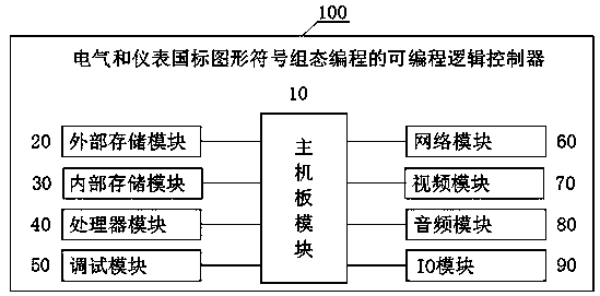
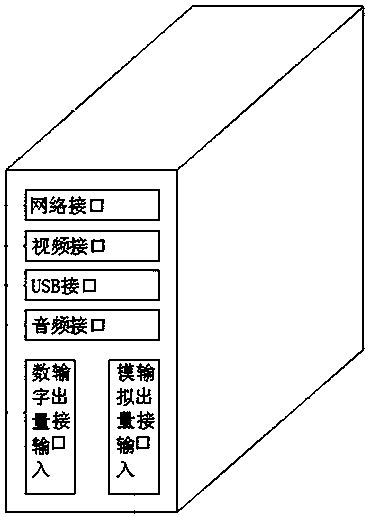
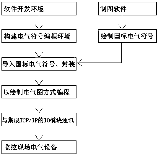
[0029] see figure 1 , figure 2 , image 3 , a control method of a programmable logic controller, carried out according to the following steps:

[0030] (1) Use drawing software to draw standard electrical and instrument national standard graphic symbols.

[0031] (2) Use development software to build a programming environment for electrical and instrumentation national standard graphic symbols.

[0032] (3) Import the drawn electrical and instrument national standard graphic symbols into the development software, and then store them uniformly in the software library of the development software.

[0033] (4) Use development software to package electrical and instrument national standard graphic symbols and back...


PUM


Abstract

The invention relates to a control method of a programmable logic controller. The method includes a method for controlling a programmable logic controller (PLC) by configuration programming using electrical and instrumentation national standard graphic symbols. By dragging symbols in a built-in graphic symbol library of a device, a program in a paper pattern electric installation style is rapidlyconfigured, and then the graphic symbols which are completed in configuration are corresponding to switching quantity input and output ports and analog quantity input and output ports of the programmable logic controller, to realize collection and port control actions. The method enables an electrical designer to configure and program a design program in the form of an electric installation drawing, to realize control of programmable logic controller. Configuration programming is simple and intuitive, and can replace ladder diagrams, sentence tables and other tedious programming methods currently used in automation engineering, so as to reduce time cost for projects, reduce difficulty of construction technology for engineering technicians, and provide a visual and simple programming interface for later maintenance personnel to modify and add ports.

Description

technical field [0001] The invention relates to the field of automatic control, in particular to a control method of a programmable logic controller. Background technique [0002] 1. The use of existing programmable logic controllers: [0003] At present, the programmable logic controllers on the market need to use professional programming software to write programs such as ladder diagrams, statement lists, and function blocks on the computer, and then download them to the programmable logic controller after compilation to realize the control of the equipment. [0004] 2. Disadvantages of existing control programmable logic controllers: [0005] 1. The design process is complicated: as mentioned above, the programmable logic controller currently used to realize circuit control needs to go through multiple departments and multiple design processes, and then the program is written by professional programmers, and finally downloaded to the system of the programmable logic cont...

Claims


Application Information

Patent Timeline
Patent Type & Authority Applications(China)
IPC IPC(8): G06F8/34G06F8/41
CPCG06F8/34G06F8/41
Inventor 闫伟
Owner 闫伟
Why Eureka
Try Eureka