Energy-saved steel pipe cutting device

A technology for cutting devices and steel pipes, which is applied in the direction of pipe shearing devices, shearing devices, and accessories of shearing machines, etc., which can solve problems such as low application value, insufficient processing accuracy, and deviation of incision positions, and achieve easy application and practical value High, wide range of effects

Inactive Publication Date: 2018-12-07
ANHUI TECHN COLLEGE OF MECHANICAL & ELECTRICAL ENG
View PDF13 Cites 8 Cited by
  • Summary
  • Abstract
  • Description
  • Claims
  • Application Information

AI Technical Summary

Problems solved by technology

But it has the following disadvantages: when cutting, only the steel pipe on the rear side of the cutting tool is clamped, and the steel pipe part that is about to be cut at the front end has no support or clamping parts, and it is easy to cause the steel pipe to vibrate due to cutting and cause the incision position to deviate. Insufficient precision; the position of the driving roller and the driving motor is fixed, and the driving roller cannot drive independently. When the end of the steel pipe moves forward to the front of the driving roller, the driving roller and the driving motor can no longer push the steel pipe, that is, the steel pipe cannot be cut in the later stage. The actual application value is low; there is no relevant limit mechanism to uniformly limit the production and processing length of the steel pipe, and the length of the steel pipe after cutting is prone to deviation

Method used


Image

  • Energy-saved steel pipe cutting device
  • Energy-saved steel pipe cutting device
  • Energy-saved steel pipe cutting device

Examples


Embodiment

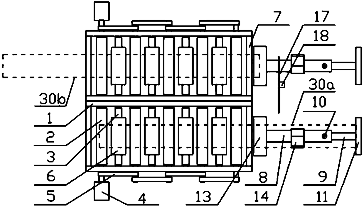
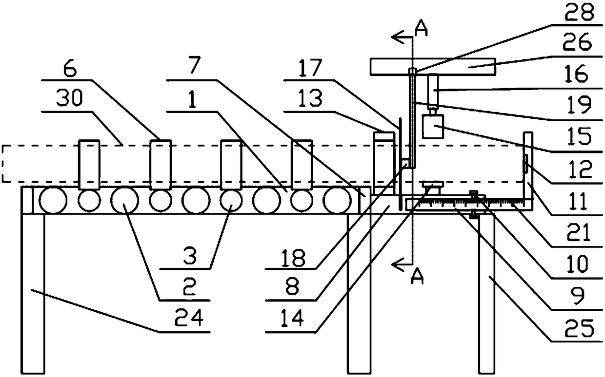
[0034] Such as figure 1 and figure 2 The shown energy-saving steel pipe cutting device includes two sets of stations for cutting steel pipes arranged side by side and a cutting mechanism reciprocating between the two sets of stations. One set of stations includes a frame, a conveyor roller row , limit adjustment components and clamping mechanism,

[0035] The conveying roller row comprises two strip-shaped frame plates 1 arranged oppositely and push roller shafts 2 and supporting roller shafts 3 which are vertically connected between the two shaped frame plates 1 and are alternately arranged at intervals. In order to push the roller shaft 2, the two ends of the push roller shaft 2 are inserted and rotatably installed on the strip frame plate 1 of the corresponding side respectively, and one end passes through the corresponding strip frame plate 1 and is placed on the strip frame plate 1. The outer side forms a driving part, the driving part of the pushing roller shaft 2 at ...


PUM


Abstract

The invention discloses an energy-saved steel pipe cutting device, and belongs to the field of steel pipe production equipment. The energy-saved steel pipe cutting device comprises two sets of stations, and a cutting mechanism for reciprocating walk between the two sets of stations; one set of station comprises a frame, a conveying roller row, a limiting adjustment module and a clamping mechanism;the conveying roller row comprises pushing roller shafts and support roller shafts alternately arranged; the pushing roller shafts are connected with rotating motors; the support roller shafts are fixed, and support pieces are fixed at the middle parts of the upper surfaces of the support roller shafts; the support pieces comprise arc groove bodies, and limiting bent rods rotationally mounted above the end parts of the arc groove bodies; a positioning plate is fixed at the tail end of the conveying roller row; an extension measuring rod is arranged in the positioning plate; a limiting plate is fixed at the end part of the extension measuring rod; the clamping mechanism comprises a fastening cylinder sleeve and a support auxiliary piece arranged on the upper surface of the positioning plate; a pressing half ring is arranged above the support auxiliary piece; and the cutting mechanism is arranged in a corresponding position between the fastening cylinder sleeve and the support auxiliarypiece. The energy-saved steel pipe cutting device can effectively prevent the incision deflection caused by vibration of steel pipes, can fully use the energy, and improves the working efficiency.

Description

technical field [0001] The invention relates to the field of steel pipe production equipment, in particular to an energy-saving steel pipe cutting device. Background technique [0002] The development of steel pipe production technology began with the rise of the bicycle manufacturing industry, the development of petroleum in the early 19th century, the manufacture of ships, boilers, and aircraft during the two world wars, the manufacture of thermal power boilers after the Second World War, and the chemical industry. The development of industry, as well as the drilling and transportation of oil and gas, have all vigorously promoted the development of the steel pipe industry in terms of variety, output and quality. The steel pipe is used to transfer fluid and powder, exchange heat and produce mechanical parts and containers, what's more it's a kind of economical steel. Using steel pipes to manufacture building structure grids, pillars and mechanical supports can reduce weigh...

Claims


Application Information

Patent Timeline
IPC IPC(8): B23D21/00B23D33/02
Inventor 丁芳漆小敏李琤张钱斌倪晋挺王波王坤岳肖飞张款张晓辉
Owner ANHUI TECHN COLLEGE OF MECHANICAL & ELECTRICAL ENG
Why Eureka
Try Eureka