
Aluminum foil printing machine

A printing machine and aluminum foil technology, applied in printing machines, rotary printing machines, printing, etc., can solve the problems of affecting the printing quality of aluminum foil, affecting the ink penetration effect, speed error, etc., to achieve enhanced inking effect, strong adhesion, good effect

Inactive Publication Date: 2018-12-07
周惠荣
View PDF0 Cites 0 Cited by
  • Summary
  • Abstract
  • Description
  • Claims
  • Application Information

AI Technical Summary

Problems solved by technology

[0003] The existing new aluminum foil printing machine has certain disadvantages in use. First, after the printing machine works for a long time, it is easy to generate increased heat inside, which has a certain impact on the work of internal components. Secondly, in the process of aluminum foil printing, It is easily affected by the ambient temperature and humidity, and deformation occurs. Due to the temperature during the working process or long-term prevention and other factors, some impurities will appear in the ink, which will affect the printing quality of the aluminum foil. There is an error in the speed of the ink leaving the ink system, which affects the ink. The penetration effect has brought a certain impact on people's production and life. Therefore, we propose an aluminum foil printing machine

Method used


Image

  • Aluminum foil printing machine
  • Aluminum foil printing machine
  • Aluminum foil printing machine

Examples


Embodiment Construction

[0018] In order to make the technical means, creative features, goals and effects achieved by the present invention easy to understand, the present invention will be further described below in conjunction with specific embodiments.

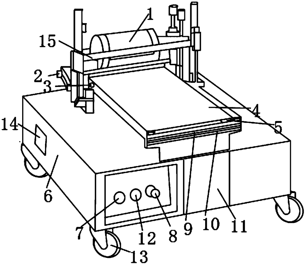
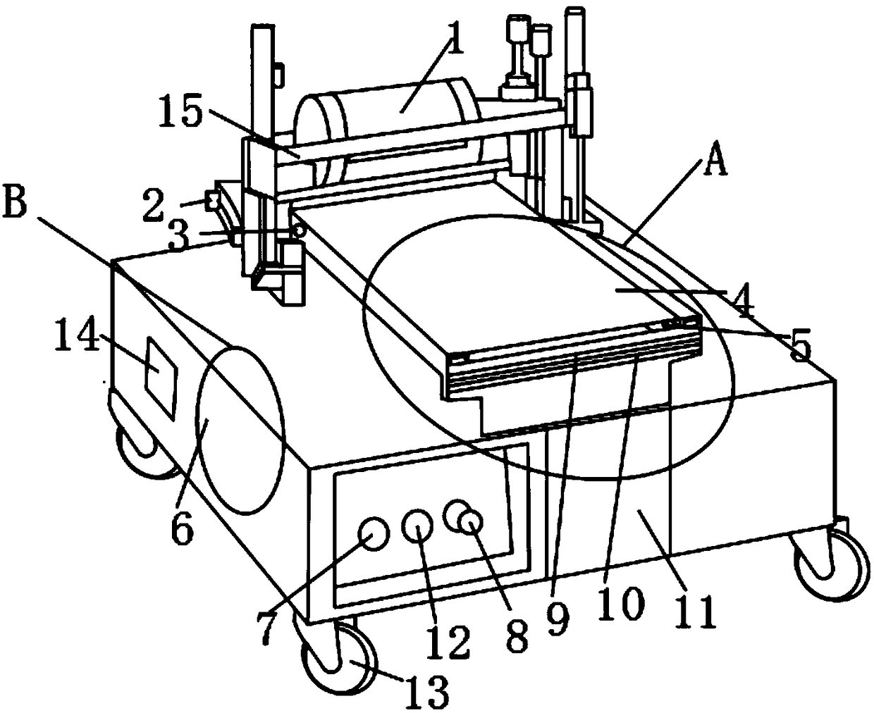
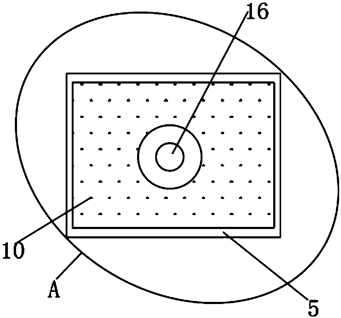
[0019] Such as Figure 1-5 As shown, an aluminum foil printing machine includes a workbench 5, a cabinet 6 and a frame 15, the upper surface of the workbench 5 is provided with a pressure plate 4, and one side of the pressure plate 4 is movably installed with a rotating shaft 2, so An aluminum foil supply drum 1 is movably installed above the rotating shaft 2, and the aluminum foil supply drum 1 is movably connected to the frame 15. The inner surface of the workbench 5 is provided with an inking device 9, and below the inking device 9 A filter screen 10 is fixedly installed, and a fault detection device 14 is fixedly mounted on one side of the cabinet 6, and a power switch 7 is provided on one side of the fault detection device 14, and a fault con...


PUM


Abstract

The invention discloses an aluminum foil printing machine. The aluminum foil printing machine comprises a workbench, a machine box and a machine frame, wherein a pressure plate is arranged on the upper surface of the workbench, and a rotating shaft is movably installed on one side of the pressure plate; an inking device is arranged on the inner surface of the workbench, and a filter screen is fixedly arranged below the inking device; a fault detection device is fixedly installed on one side of the machine box, a temperature detector is arranged on one side of the workbench, and a pressure device is movably arranged inside the workbench; and the lower surface of the filter screen is movably provided with an impurity collecting device. According to the aluminum foil printing machine, a cooling fan, the filter screen and the pressure device are arranged so that rapid heat dissipation can be carried out on the interior of the printing machine, and deformation of an aluminum foil can be prevented; impurities in the ink are filtered, so that the printing effect is prevented from being influenced, moreover, ink printing can be facilitated, then the printing effect is better; and the printing machine is suitable for different working conditions, and better application prospect is brought.

Description

technical field [0001] The invention relates to the field of printing machines, in particular to an aluminum foil printing machine. Background technique [0002] A printing press is a machine that prints text and images. Modern printing presses are generally composed of mechanisms such as plate loading, ink application, embossing, and paper feeding. Its working principle is: first make the printing plate of the text and image to be printed, install it on the printing machine, and then apply the ink to the place where the text and image are on the printing plate manually or by the printing machine, and then transfer it directly or indirectly Printing onto paper or other substrate to reproduce the same print as the printing plate. Classified according to the printing plate form, it is divided into letterpress, lithographic, gravure and stencil printing machines; the mounting plate and embossing structure is divided into flat press flat type, circular press flat type and rota...

Claims


Application Information

Patent Timeline
Patent Type & Authority Applications(China)
IPC IPC(8): B41F13/00B41F17/00B41F31/00F25D1/00
CPCB41F17/00B41F13/00B41F31/00B41F33/00F25D1/00
Inventor 周惠荣
Owner 周惠荣
Learn More