
Industrial high-efficiency wastewater treatment device

A technology for wastewater treatment and industrial use. It is used in water/sewage multi-stage treatment, water/sludge/sewage treatment, fixed filter element filters, etc. problem, to achieve the effect of reasonable structure setting, good fixing effect and good use effect

Active Publication Date: 2018-12-07
YUHUAN JINLONG KLOE SANITARY WARE
View PDF5 Cites 2 Cited by
  • Summary
  • Abstract
  • Description
  • Claims
  • Application Information

AI Technical Summary

Problems solved by technology

[0003] 1. The general wastewater treatment device does not have a buffer. When treating wastewater, the wastewater directly enters the inside of the treatment tank, and the wastewater directly pours into the inside of the treatment tank at one time. The impact force is relatively large, and part of the wastewater is not treated directly. Discharge, making the effect of wastewater treatment poor;
[0004] 2. There is high-temperature wastewater in industrial wastewater, and the high-temperature wastewater is directly treated without cooling. Excessive temperature will affect the normal use of the internal components of the treatment tank, and the discharged wastewater will cause damage to the staff if the temperature is too high, which is relatively safe. Difference;
[0005] 3. Generally, the installation method of the filter screen inside the treatment tank is relatively simple. Usually, it is fixed by screw connection, which is time-consuming and laborious. After a long time of contact with water, the screws are prone to rust and slip, which affects the fixing effect, and even the filter screen cannot be fixed. to disassemble

Method used


Image

  • Industrial high-efficiency wastewater treatment device
  • Industrial high-efficiency wastewater treatment device
  • Industrial high-efficiency wastewater treatment device

Examples


Embodiment Construction

[0027] The following will clearly and completely describe the technical solutions in the embodiments of the present invention with reference to the accompanying drawings in the embodiments of the present invention. Obviously, the described embodiments are only some, not all, embodiments of the present invention. Based on the embodiments of the present invention, all other embodiments obtained by persons of ordinary skill in the art without making creative efforts belong to the protection scope of the present invention.

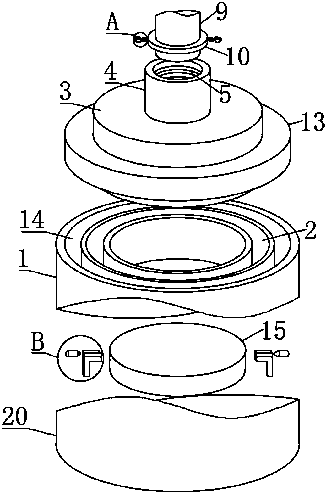
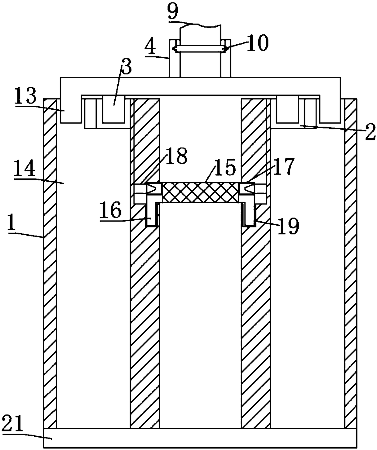
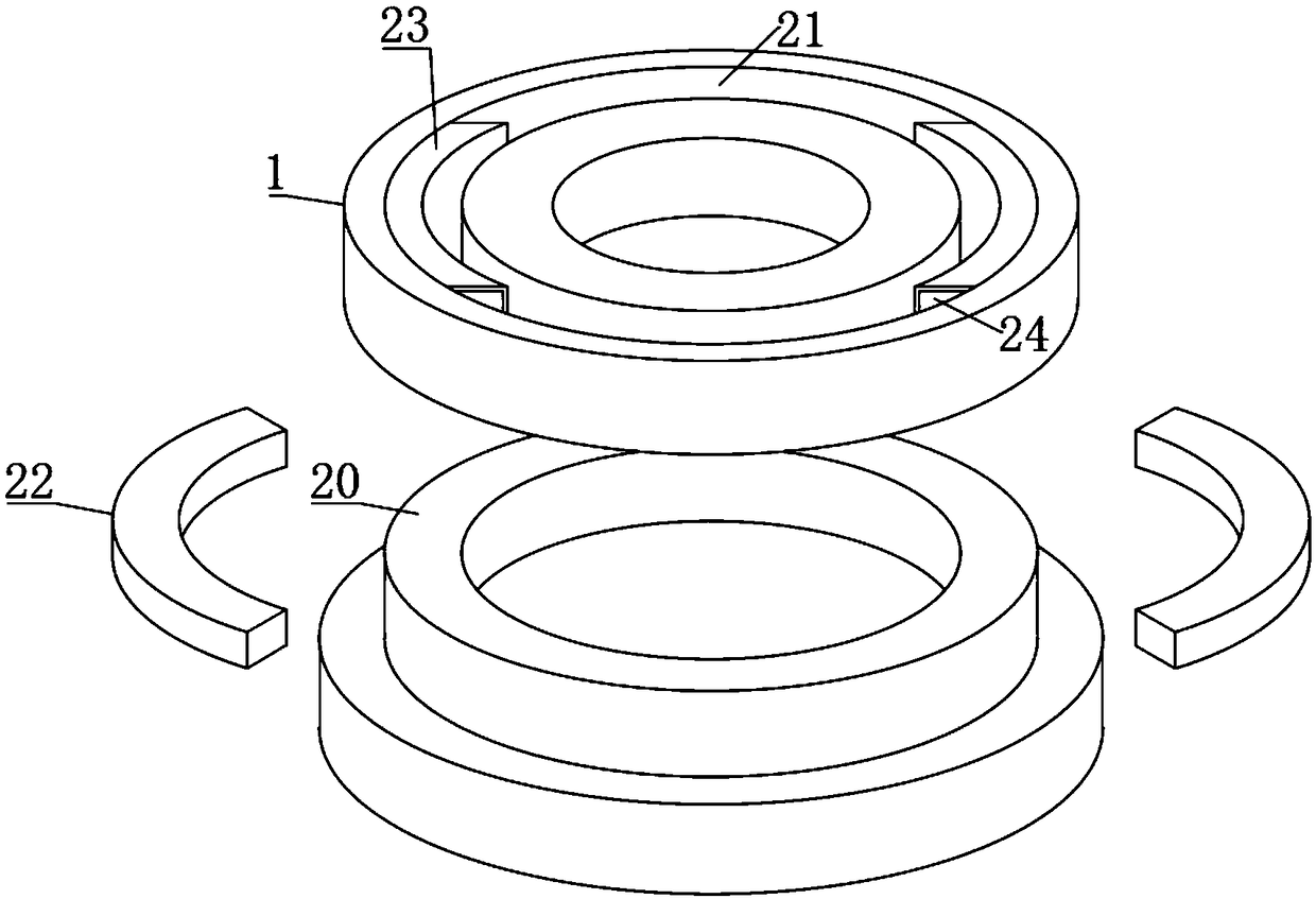
[0028] see Figure 1-8 , the present invention provides a technical solution: an industrial high-efficiency wastewater treatment device, comprising a treatment tank 1, a sealing top plate 3, a connecting pipe 9 and a sealing bottom plate 20, the inside of the treatment tank 1 is provided with a fixing groove 2, and the fixing groove 2 The inside of the sealing top plate 3 is clamped, and the surface of the sealing top plate 3 is fixedly connected with the conn...


PUM


Abstract

The invention discloses an industrial high-efficiency wastewater treatment device which comprises a treatment tank, a sealed top plate, a connecting pipe and a sealed bottom plate, wherein a fixing groove is formed inside the treatment tank; flow-limiting plates are fixedly connected inside the mounting groove; an elastic piece is fixedly connected inside a clamping piece; the surface of the sealed top plate is fixedly connected with a fixed lantern ring; a cooling tank is arranged inside the treatment tank; the fixed lantern ring is clamped inside the cooling tank; a filter plate is clamped inside the treatment tank; the sealed bottom plate is clamped at the lower end of the treatment tank; a sealing groove is formed inside the treatment tank; a slide chute is formed inside the fixing piece; the fixing plate is clamped inside the slide chute; and the clamping piece is fixedly connected to the surface of the filter plate. The clamping piece is clamped inside the connecting groove, thefilter plate is preliminarily fixed, and the limiting piece is clamped inside the limiting groove, so that the filter plate is subjected to secondary fixation, the fixing effect is excellent, the filter plate is convenient to detach, and the treatment device is simple in structure and suitable for popularization.

Description

technical field [0001] The invention relates to the technical field of industrial wastewater treatment, in particular to an industrial high-efficiency wastewater treatment device. Background technique [0002] Industrial wastewater includes production wastewater and production sewage, which refers to wastewater and waste liquid generated in the process of industrial production. With the rapid development of industry, the pollution of water bodies is becoming more and more extensive and serious, threatening human health and safety. Therefore, for the protection of In terms of the environment, the treatment of industrial wastewater is more important than the treatment of urban sewage. Wastewater treatment equipment is required to treat the wastewater in order to achieve the purpose of easy operation, but it still has the following disadvantages in actual use: [0003] 1. The general wastewater treatment device does not have a buffer. When treating wastewater, the wastewater di...

Claims


Application Information

Patent Timeline
IPC IPC(8): C02F9/08
CPCB01D29/03B01D29/96
Inventor 梅勇康竹洪燕韩玲
Owner YUHUAN JINLONG KLOE SANITARY WARE
Features
  • Generate Ideas
  • Intellectual Property
  • Life Sciences
  • Materials
  • Tech Scout
  • Unparalleled Data Quality
  • Higher Quality Content
  • 60% Fewer Hallucinations
Learn More