Turnover type clothes hanger
A clothes drying rack and flip technology, applied in the field of clothes drying racks, can solve the problems of limited application scope, insufficient strength, small drying space, etc., and achieve the effects of wide application scope, small footprint and high installation strength
- Summary
- Abstract
- Description
- Claims
- Application Information
AI Technical Summary
Problems solved by technology
Method used
Image
Examples
Embodiment 1
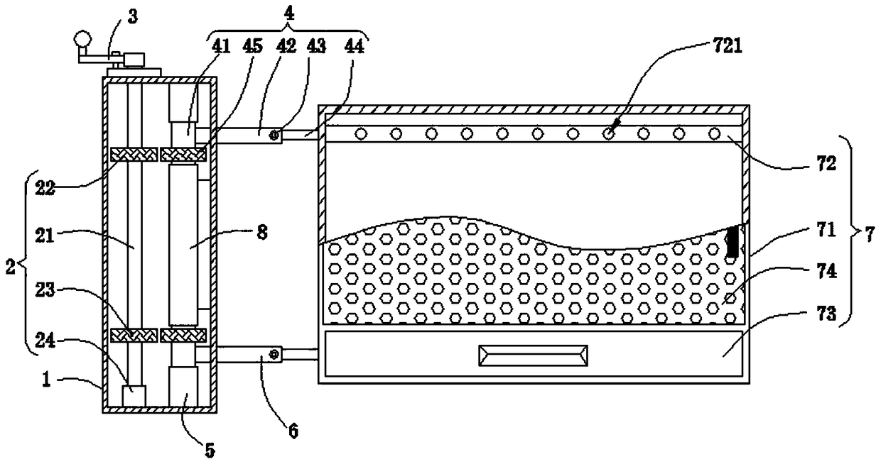
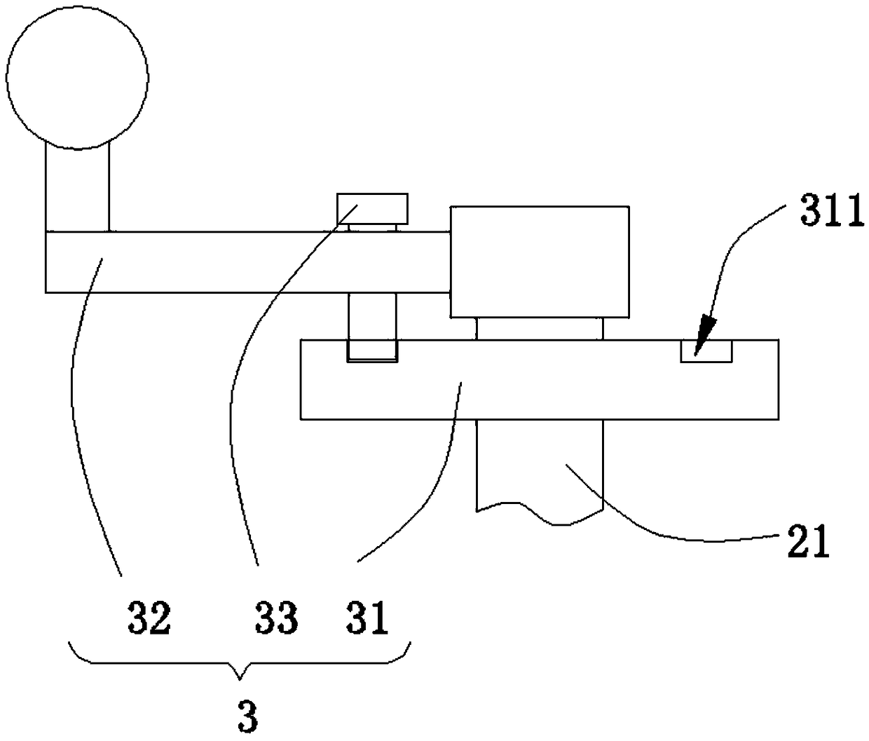
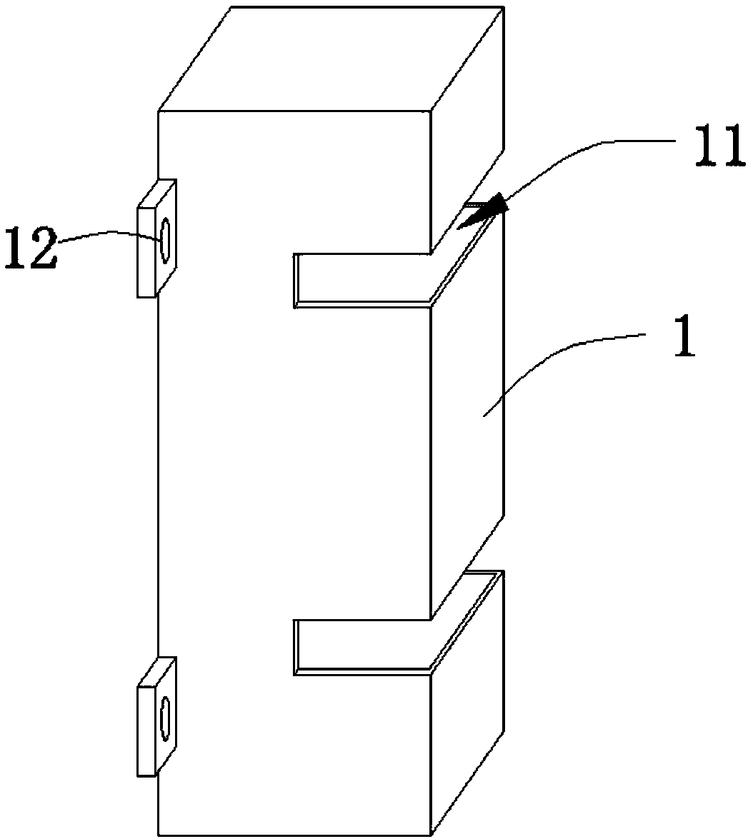
[0035] When the mounting plate 12 is welded on the side of the mounting pipe 1, the mounting plate 12 is fixed on the side wall of the balcony by screws, so that the mounting pipe 1 is hung on the wall of the balcony; the user can open the cover plate 74, and the clothes hanger The crotch of the hook passes through the hanging hole 721, and the clothes are hung on the bottom of the hanging rod 72 successively, and the cover plate 74 is covered after the suspension is completed; the handle 32 is turned to drive the transmission rod 21 to rotate, so that the first gear 22, the second The gears 23 rotate synchronously, and the third gear 45 rotates synchronously under the action of the meshing force, so that the connecting pipe 41 rotates around the second casing 5 and the rotating column 8, and the rotation of the support mechanism drives the protection box 71 to rotate outwards as a whole, so that the protection box 71 stretches out, and when stretched out to a suitable position...
Embodiment 2
[0037] When the mounting plate 12 is welded on the bottom surface of the mounting pipe 1, the mounting plate 12 is fixed on the bottom concrete floor of the balcony by screws, so that the mounting pipe 1 is vertically fixed on the ground of the balcony; the user can open the cover plate 74, and the clothes hanger The crotch of the hook passes through the hanging hole 721, and the clothes are hung on the bottom of the hanging rod 72 successively, and the cover plate 74 is covered after the suspension is completed; the handle 32 is turned to drive the transmission rod 21 to rotate, so that the first gear 22, the second The gears 23 rotate synchronously, and the third gear 45 rotates synchronously under the action of the meshing force, so that the connecting pipe 41 rotates around the second casing 5 and the rotating column 8, and the rotation of the support mechanism drives the protection box 71 to rotate outwards as a whole, so that the protection box 71 stretches out, and when ...
PUM
 Abstract
Description
Claims
Application Information
 - R&D
- Intellectual Property
- Life Sciences
- Materials
- Tech Scout
- Unparalleled Data Quality
- Higher Quality Content
- 60% Fewer Hallucinations
Browse by: Latest US Patents, China's latest patents, Technical Efficacy Thesaurus, Application Domain, Technology Topic, Popular Technical Reports.
© 2025 PatSnap. All rights reserved.Legal|Privacy policy|Modern Slavery Act Transparency Statement|Sitemap|About US| Contact US: help@patsnap.com


