Bathroom floor paving structure

A toilet and floor technology, applied in indoor sanitary pipeline installations, water supply installations, buildings, etc., can solve the problems of floor tiles without water seepage, water guide, slipping, and large water consumption, and achieve significant water saving effects

Pending Publication Date: 2018-12-07
YANGZHOU POLYTECHNIC COLLEGE
View PDF5 Cites 0 Cited by
  • Summary
  • Abstract
  • Description
  • Claims
  • Application Information

AI Technical Summary

Problems solved by technology

[0002] The drainage problem of the bathroom floor is usually the most problem to be solved in the bathroom floor pavement. When the existing bathroom floor is paved, it is necessary to set a certain slope on the bathroom floor so that the water can flow to the direction of the floor drain along the slope, so that the toilet floor Water discharge, the floor tile itself does not have the function of water seepage and water conduction, and it is easy to cause people to slip and fall when the ground water flow is not timely or the slope is not enough
At the same time, the water consumption in the shower is very large, and the shower water directly flows into the drainage system through the floor drain, and a large amount of water is not properly utilized, resulting in a large amount of waste

Method used


Image

  • Bathroom floor paving structure
  • Bathroom floor paving structure
  • Bathroom floor paving structure

Examples


Embodiment 1

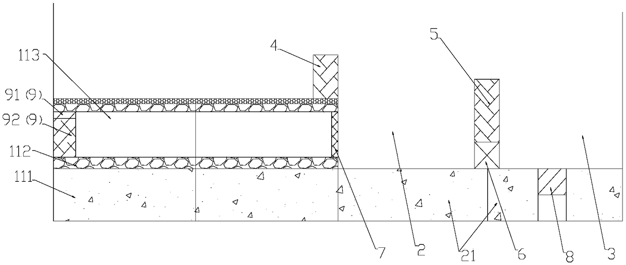
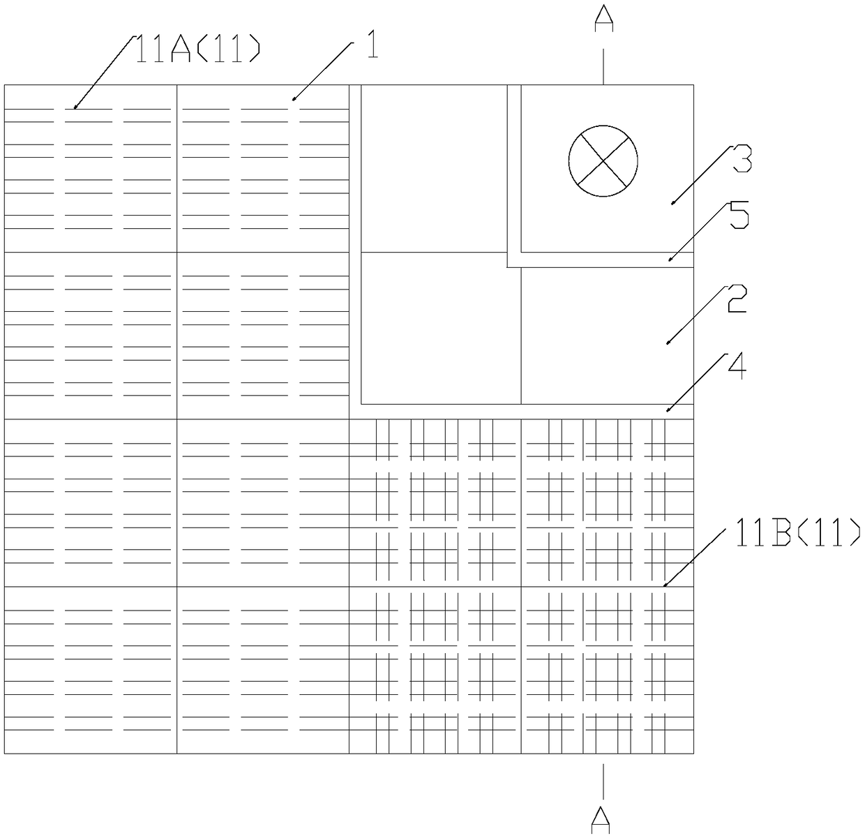
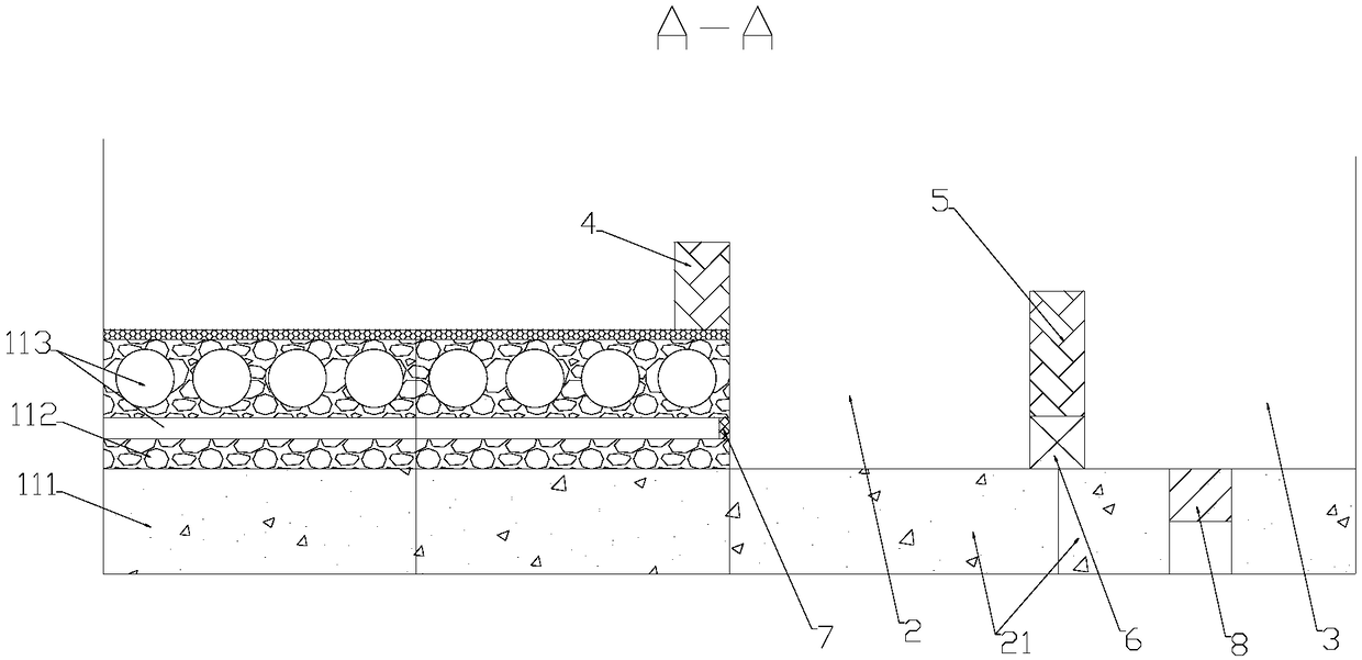
[0024] Such as figure 1 , figure 2 Shown is a specific embodiment of the bathroom floor pavement structure provided by the present invention, the pavement structure includes a water filtration water diversion area 1, a water collection area 2 and a drainage area 3; the water filtration water diversion area 1 and the described The water collection area 2 is separated by the first isolation brick 4, and the water collection area 2 and the drainage area 3 are isolated by the second isolation brick 5; The water filter floor tile 11 includes an anti-seepage layer 111 and a water-permeable layer 112 arranged on the upper side of the anti-seepage layer. The water-permeable layer 112 is provided with a water guide hole 113 inside, and the water guide hole 113 is suitable for guiding water to the In the water collection area 2, an on-off valve 6 is provided on the second isolation brick 5.

[0025] Specifically, the water-permeable layer 112 is a porous structure, which includes a w...

Embodiment 2

[0034] Such as image 3It is another specific embodiment of the bathroom floor pavement structure. The pavement structure is basically the same as that of Example 1, the difference is that in this embodiment, the water guide holes 113 in the bidirectional water guide brick 11B are on the same layer, that is, the horizontal guide The water holes and the longitudinal water guide holes are perpendicular to each other and communicate with each other. In addition, in order to avoid the problem of water stagnation in the water guide hole, a magnetic water guide 9 is provided inside the water guide hole 113, and the outer peripheral surface of the magnetic water guide member 9 is attached to the inner surface of the water guide hole 113, And the magnetic water guide 9 can slide along the water guide hole 113 under the action of magnetic force, so that the magnetic water guide 9 can be attracted by the magnetic parts outside the floor tiles, and the magnetic water guide 9 can be guide...


PUM


Abstract

The invention discloses a bathroom floor paving structure and belongs to the field of building construction. The floor paving structure includes a water filtering water guiding area, a water collecting area and a water drainage area; the water guiding water guiding area and the water collecting area are separated by a first isolation brick, the water collecting area and the water drainage area areseparated by a second isolation brick, the water filtering water guiding area includes water filtering floor tiles, each water filtering floor tile includes an impervious barrier and a water-permeable layer disposed on the upper side of the impervious barrier, the water-permeable layer is internally provided with water guiding holes, the water guiding holes are adapted to guide water to the watercollecting area, and the second isolation brick is provided with an on-off valve. The bathroom floor paving structure solves the technical problems that the existing paving structure cannot achieve water seepage and cause the ground is slippery and shower water cannot be used secondarily, and bathroom floor paving structure is particularly suitable for bathroom floor paving of ordinary households.

Description

technical field [0001] The invention belongs to the field of building construction, and in particular relates to a bathroom floor pavement structure. Background technique [0002] The drainage problem of the bathroom floor is usually the most problem to be solved in the bathroom floor pavement. When the existing bathroom floor is paved, it is necessary to set a certain slope on the bathroom floor so that the water can flow to the direction of the floor drain along the slope, so that the toilet floor The floor tile itself does not have the function of water seepage and water conduction, and it is easy to cause people to slip and fall when the ground water flow is not timely or the slope is not enough. Simultaneously, water consumption is very large during shower, and shower water directly flows into drainage system through floor drain, and a large amount of water is not utilized rationally, has caused a large amount of wastes. Contents of the invention [0003] For this re...

Claims


Application Information

Patent Timeline
Patent Type & Authority Applications(China)
IPC IPC(8): E03C1/01E03C1/122E03C1/16
CPCE03C1/01E03C1/122E03C1/16
Inventor 闫志刚
Owner YANGZHOU POLYTECHNIC COLLEGE
Why Eureka
Try Eureka