Pneumatic elastic sealing device and gas turbine engine

A gas turbine and engine technology, applied to engine components, jet propulsion devices, machines/engines, etc., can solve problems such as cold and hot air mixing losses, cooling air leakage, gas leakage, etc., to reduce the sealing leakage area and compensate Thermal deformation and expansion, the effect of improving sealing efficiency

Active Publication Date: 2018-12-07
AECC SHENYANG ENGINE RES INST
View PDF6 Cites 3 Cited by
  • Summary
  • Abstract
  • Description
  • Claims
  • Application Information

AI Technical Summary

Problems solved by technology

The cooling air of the gas turbine engine itself leaks into the gas flow path of the turbine through the installation gap between the stator components at the boundary of the gas flow path of the turbine, and excessive cooling air leaks into the gas flow path of the turbine at an angle nearly perpendicular to the mainstream gas, causing Local gas flow turbulence, coupled with the loss of mixing hot and cold air, results in reduced turbine efficiency and consequently reduced engine performance
[0003] At present, for the sealing of this kind of situation, the bolt tight connection sealing structure is widely used. The bolt connection tight sealing structure is to directly connect the stator parts at the boundary of the turbine gas flow channel through bolts to form a closed cylinder. Block gas from leaking through the boundary. Although the bolted connection structure can achieve a tight seal between the stator parts of the turbine gas flow channel boundary, it needs to carefully consider the thermal deformation in the radial and axial directions. The thermal design is very difficult. A lot of work needs to be carried out in terms of performance matching and connection structure design, otherwise problems such as thermal fatigue, deformation, and cracks will easily occur. Moreover, if you work in a high-temperature environment for a long time, the connection is easy to stick and difficult to decompose. Due to the roughness of the surface of the parts In fact, it is difficult to achieve a complete seal between the two parts connected by bolts. The gas pressure inside the gas flow channel is much higher than that on the outside, and the gas will inevitably leak from the gap of the mating surface of the bolted connection, resulting in overheating of the material and causing a series of problems.

Method used


Image

  • Pneumatic elastic sealing device and gas turbine engine
  • Pneumatic elastic sealing device and gas turbine engine
  • Pneumatic elastic sealing device and gas turbine engine

Examples


Embodiment Construction

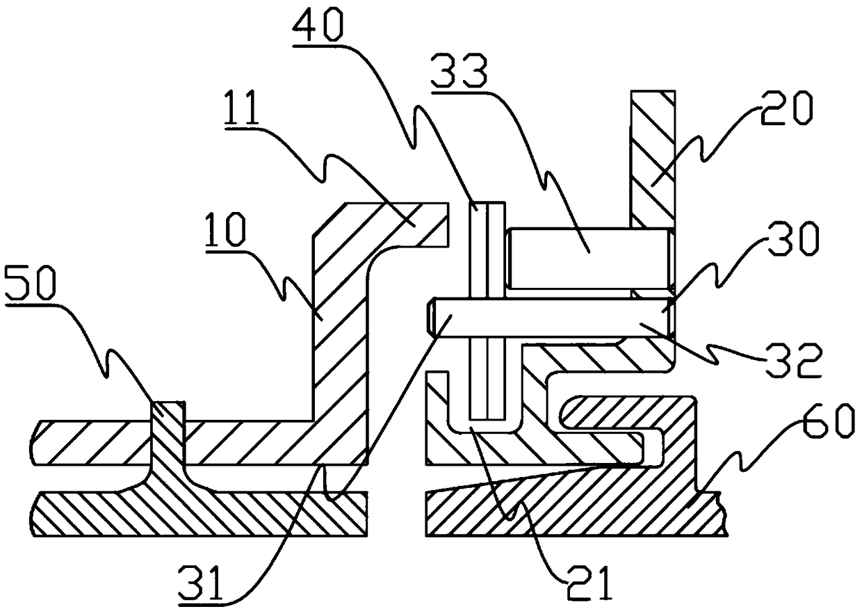
[0023] To make the objectives, technical solutions, and advantages of the implementation of the present invention clearer, the technical solutions in the embodiments of the present invention will be described in more detail below in conjunction with the accompanying drawings in the embodiments of the present invention. In the drawings, the same or similar reference numerals indicate the same or similar elements or elements with the same or similar functions. The described embodiments are part of the embodiments of the present invention, but not all of the embodiments. The embodiments described below with reference to the accompanying drawings are exemplary, and are intended to explain the present invention, but should not be construed as limiting the present invention. Based on the embodiments of the present invention, all other embodiments obtained by those of ordinary skill in the art without creative work shall fall within the protection scope of the present invention. The ...


PUM


Abstract

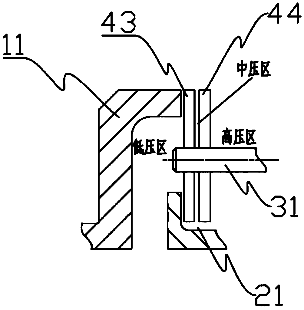
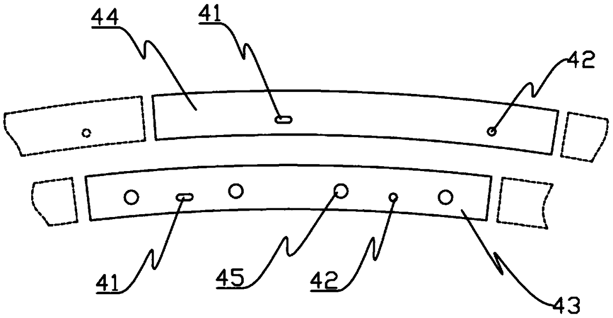
The invention discloses a pneumatic elastic sealing device and a gas turbine engine. The pneumatic elastic sealing device comprises a first outer ring, a second outer ring, a positioning component anda sealing component. The first outer ring and the second outer ring are arranged oppositely, and an accommodating cavity is formed between the first outer ring and the second outer ring. The first outer ring is provided with an annular boss. The second outer ring is provided with an annular limiting groove. The positioning component is arranged on the second outer ring, extends towards the firstouter ring in the axial direction of the second outer ring and is at least partially located in the accommodating space, and the portion, located in the accommodating space, of the positioning component is called a guide section. The sealing component is arranged on the guide section. The gas turbine engine comprises the pneumatic elastic sealing device. According to the pneumatic elastic sealingdevice and the gas turbine engine, two layers of sealing pieces are connected in series, and fan-shaped notches of the two layers of sealing pieces are arranged in a staggered mode, so that the leakage area is greatly reduced, the sealing efficiency is improved, and installation is convenient.

Description

Technical field [0001] The invention belongs to the technical field of aeroengines, and specifically relates to a pneumatic elastic sealing device and a gas turbine engine. Background technique [0002] Advanced sealing technology has the characteristics of low investment and high return for gas turbine engines. Compared with the way to improve engine performance through improved blade structure design, the cost of adopting advanced sealing technology is much lower under the conditions of similar effect. With the improvement of the design level of gas turbine engines, more and more attention has been paid to the influence of static seals between gas runner boundary components on the overall performance and efficiency of the engine. The cooling air of the gas turbine engine itself leaks to the turbine gas flow channel through the installation gap between the stator parts on the boundary of the turbine gas flow channel. Excess cooling air leaks into the turbine gas flow channel at ...

Claims


Application Information

Patent Timeline
Patent Type & Authority Applications(China)
IPC IPC(8): F01D11/02F02C7/28
CPCF01D11/003F01D11/02F02C7/28
Inventor 赵家军杨守辉赵耘墨邓明春陆海鹰范宇段玉发熊玉宋辰星
Owner AECC SHENYANG ENGINE RES INST
Why Eureka
Try Eureka