Supercharge Your Innovation With Domain-Expert AI Agents!

Diaphragm sleeve and steam turbine

A diaphragm sleeve and steam turbine technology, applied in mechanical equipment, engine components, machines/engines, etc., can solve the problems of large axial size and complex structure, and achieve the goal of reducing axial size, simplifying structure, and reducing manufacturing costs Effect

Pending Publication Date: 2018-12-07
CHINA CHANGJIANG ENERGY CORP GROUP
View PDF6 Cites 0 Cited by
  • Summary
  • Abstract
  • Description
  • Claims
  • Application Information

AI Technical Summary

Problems solved by technology

[0005] The purpose of the present invention is to provide a partition sleeve to solve the technical problem of the cylinder in the prior art with large axial size and complex structure

Method used


Image

  • Diaphragm sleeve and steam turbine
  • Diaphragm sleeve and steam turbine
  • Diaphragm sleeve and steam turbine

Examples


Embodiment 1

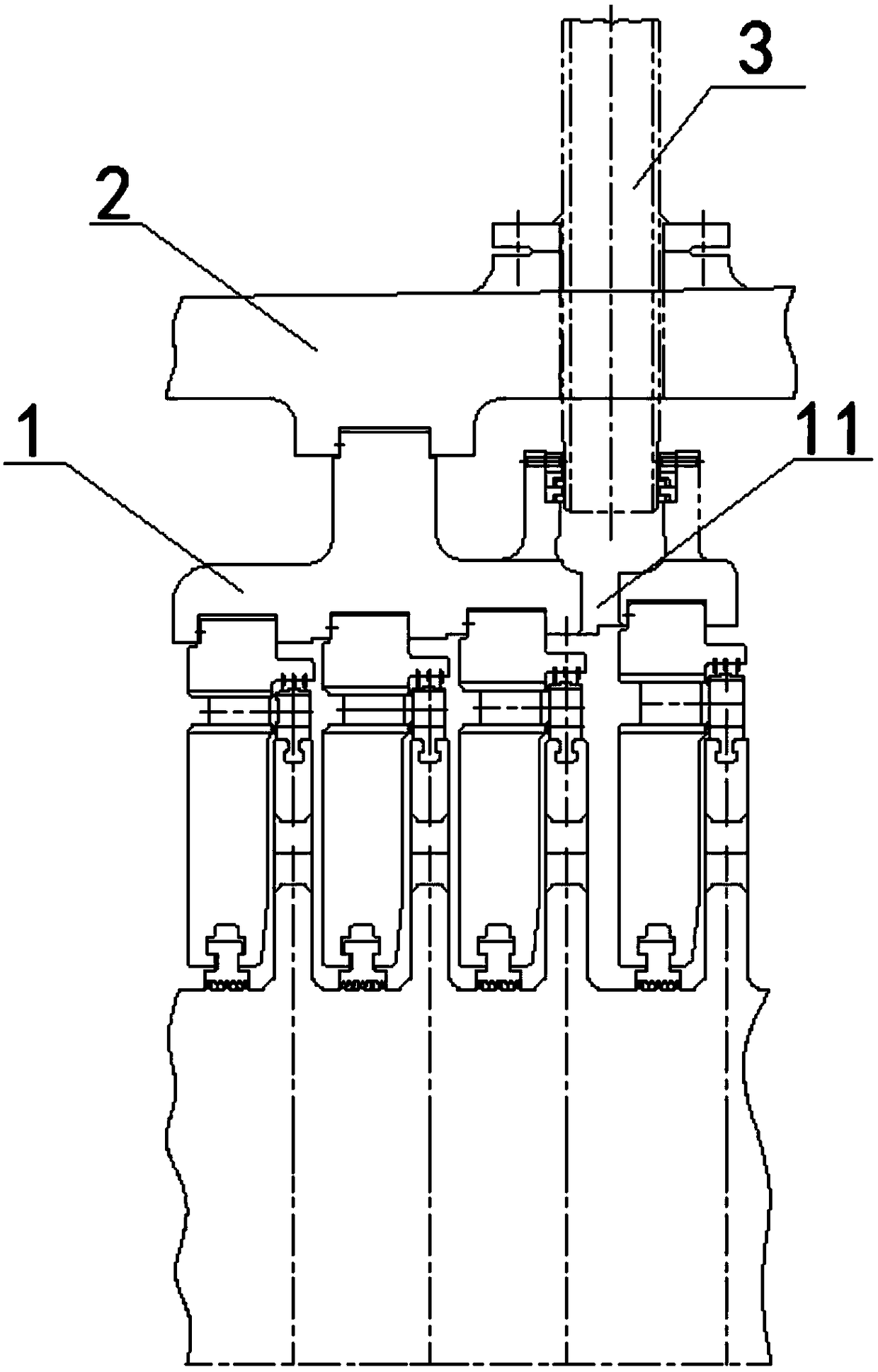
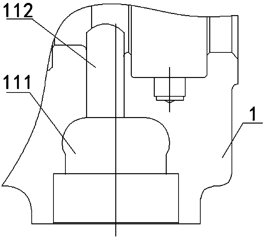
[0033] The partition cover provided in this embodiment, such as Figure 2 to Figure 5 As shown, the first partition cover 1 is included; the inner wall of the first partition cover 1 is provided with a plurality of partition installation grooves, and the side wall of the first partition cover 1 is provided with a steam extraction hollow mechanism. The two ends of the structure 11 are respectively arranged through the side wall of the first baffle cover 1 , and the steam extraction hollow structure 11 is located between two adjacent baffle installation grooves.

[0034] Wherein, the shape of the hollow air pumping structure is determined according to the size of the hole obtained through the calculation of the flow, such as any suitable shape such as column, arc or cavity, and the two ends of the air pumping hollow structure penetrate through the side wall of the first partition sleeve 1 respectively. Setting, the inner wall and the outer wall of the first partition cover 1 can...

Embodiment 2

[0051] The steam turbine provided by the present embodiment comprises a cylinder 2, a front steam seal, a connecting pipe 3 and a partition cover of the present invention; the partition cover is fixed on the inner wall of the cylinder 2, and one end of the connecting pipe 3 communicates with the steam extraction hollow structure 11, The other end passes through the cylinder 2 and communicates with the front steam seal.

[0052] Wherein, the air pumping hollow structure can be in any suitable shape, such as any suitable shape such as columnar, arc-shaped or cavity-shaped, and the two ends of the air pumping hollow structure are respectively set through the side wall of the first partition cover 1, which can be used The inner wall and the outer wall of a partition cover 1 are connected, so that the steam extracted from the front steam seal enters between the two partitions of the partition cover through the connecting pipe 3 on the cylinder 2 and the steam extraction hollow struc...


PUM


Abstract

The invention provides a diaphragm sleeve and a steam turbine, and relates to the technical field of power machinery. The diaphragm sleeve comprises a first diaphragm sleeve; multiple diaphragm mounting grooves are formed in the inner side wall of the first diaphragm sleeve; a steam extraction hollow mechanism is arranged on the side wall of the first diaphragm sleeve; two ends of the steam extraction hollow mechanism penetrate through the side walls of the first diaphragm sleeve; and the steam extraction hollow mechanism is positioned between two adjacent diaphragm mounting grooves. The steamextraction hollow mechanism can communicate with a front steam seal through a connecting pipe, so that steam is directly fed between the two adjacent diaphragms through a proper position on the firstdiaphragm sleeve by the front steam seal; and through the arrangement, the adding of the diaphragm sleeve in a cylinder is not needed, the axial size of the cylinder can be reduced, the structure ofthe cylinder is simplified, and the production cost is reduced.

Description

technical field [0001] The invention relates to the technical field of power machinery, in particular to a baffle cover and a cylinder with the baffle cover. Background technique [0002] A steam turbine is a rotating power machine that converts the energy of steam into mechanical work. Also known as steam turbine. It is mainly used as a prime mover for power generation, and can also directly drive various pumps, fans, compressors and ship propellers. It is also possible to use the exhaust steam or intermediate steam extraction of the steam turbine to meet the heating needs of production and life. [0003] At present, the main function of the diaphragm sleeve 1' used in domestic steam turbines is to fix the diaphragm, so that the distance between stages is not or less affected by the steam extraction port of the cylinder, so that the axial size of the steam turbine is relatively reduced. In addition, the shape of the cylinder 2' can be simplified, which is convenient for ...

Claims


Application Information

Patent Timeline
Patent Type & Authority Applications(China)
IPC IPC(8): F01D25/24
CPCF01D25/24F01D25/246
Inventor 瞿灿隋正王达君彭博刘一方张颖刘佳徐伟蒋贤耀
Owner CHINA CHANGJIANG ENERGY CORP GROUP
Features
  • R&D
  • Intellectual Property
  • Life Sciences
  • Materials
  • Tech Scout
  • Unparalleled Data Quality
  • Higher Quality Content
  • 60% Fewer Hallucinations
Learn More