Multifunctional water body moving power device

A power plant and multi-functional technology, applied in the field of energy-saving and environmental protection equipment, can solve the problems of single use, large energy consumption, and no development of liquid characteristics, and achieve the effects of wide use, many use environments and simple structure

Active Publication Date: 2018-12-07
EAST CHINA UNIV OF TECH
View PDF4 Cites 1 Cited by
  • Summary
  • Abstract
  • Description
  • Claims
  • Application Information

AI Technical Summary

Problems solved by technology

[0002] Submersible pump is a widely used mechanical device, but it has three problems, 1. High energy consumption; 2. Single purpose; 3. Only use liquid for lubrication and cooling in a liquid environment, without developing liquid characteristics, and use liquid as resistance treat

Method used


Image

  • Multifunctional water body moving power device
  • Multifunctional water body moving power device
  • Multifunctional water body moving power device

Examples


Embodiment 1

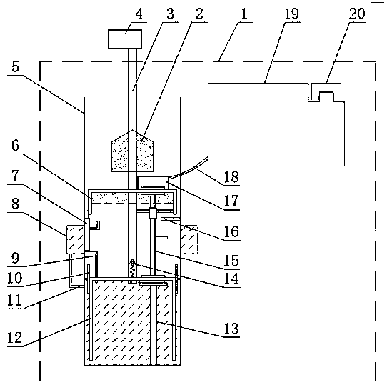
[0040] Such as Figure 1-6 As shown, a multifunctional water body moving power unit includes a power unit 4 and a power bar 3 for lifting and driving, and the power bar 3 is connected with the power unit 4, and also includes a box body 5 located in the water body 1, a partition plate 10, Expansion body 12, communication valve 15, exhaust valve 7, annular ventilation chamber 8, intake and exhaust balance float 6, closed balance float 2; the bottom of the box body 5 is provided with a partition plate 10 that is sealingly matched with the expansion body 12, and the interval The plate 10 is fixed on the box body 5, the expansion body 12 is connected with the power rod 3, the power rod 3 is provided with an air inlet leading to the outside of the water body 1, and a check valve 14 is installed at the bottom of the air inlet; The connecting valve 15 of the body 12 and the intake and exhaust balance float 6 is installed on the expansion body 12 and the intake and exhaust balance floa...

Embodiment 2

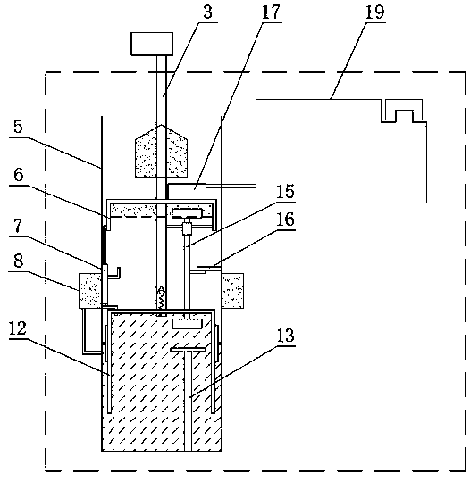
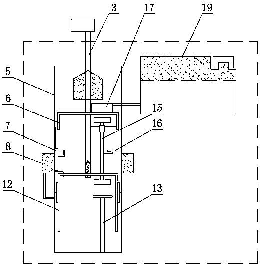
[0043] Such as Figure 7 As shown, on the basis of the technical solution of Embodiment 1, the water body 1 is located in the box body 5, and the box body 5 is located on the ground; the closed balance float 2 can be switched between the float and the counterweight body, and this embodiment applies on the ground. The ventilation principle of this embodiment is the same as that of Embodiment 1. During the first stage of the stroke, the liquid level of the upper water body is at the lowest point; during the second stage of the stroke, the water level of the upper water body is at the highest point; The air in the float is discharged through the air duct, and the expansion body loses the balance of the buoyancy of the float and the upward pull of the power rod, and moves downward under the action of gravity, and the water level of the upper water body is at the highest point; The water is re-divided into upper and lower independent water bodies, the air in the annular ventilatio...


PUM


Abstract

The invention belongs to the technical field of energy-saving and environment-friendly equipment, particularly relates to a multifunctional water body moving power device. The device comprises a powerdevice and a power rod, and further comprises a box body, a partition plate, an expansion body, a communication valve, an exhaust valve annular ventilation bin, an air intake and exhaust balance floater and a closed balance floater, wherein the box body, the partition plate, the expansion body, the communication valve, the exhaust valve annular ventilation bin, the air intake and exhaust balancefloater and the closed balance floater are located in a water body; the bottom of the box body is provided with the partition plate which is in sealed fit with the expansion body, a one-way valve is installed at the bottom of an air inlet hole in the power rod, and the communication valve is installed on the expansion body and the air intake and exhaust balance floater; and a bypass pipe and an air inlet pipe of the exhaust valve annular ventilation bin are connected with the bottom of the box body and the top end of the expansion body respectively, an exhaust valve of the annular ventilationbin is installed in the box body, an air guide pipe is arranged above the air intake and exhaust balance floater, and the air guide pipe is connected with an air cavity on the air intake and exhaust balance floater. The device can exist in two environments such as the ground and a water bottom, wherein a liquid level fluctuation device and a liquid lifting device are ground environment equipment,and a main body underwater gas supply device is positioned in a water bottom environment.

Description

technical field [0001] The invention belongs to the technical field of energy-saving and environment-friendly equipment, and in particular relates to a multifunctional water body moving power device. Background technique [0002] Submersible pump is a widely used mechanical device, but it has three problems, 1. High energy consumption; 2. Single purpose; 3. Only use liquid for lubrication and cooling in a liquid environment, without developing liquid characteristics, and use liquid as resistance treat. Therefore, in order to overcome the above-mentioned technical defects, a multifunctional water body moving power device is designed. The device takes the liquid environment as the main field, uses external power to promote the water body moving, and uses the energy generated by the moving to reduce energy consumption and resistance. Under the premise of ensuring the benefits, the existing problems of submersible pumps are completely overcome, and the function and application ...

Claims


Application Information

Patent Timeline
Patent Type & Authority Applications(China)
IPC IPC(8): F04B19/04
Inventor 梁也
Owner EAST CHINA UNIV OF TECH
Why Eureka
Try Eureka