A New Electrohydraulic Push Rod

An electro-hydraulic push rod, a new type of technology, applied in the direction of electromechanical devices, electrical components, electric components, etc., can solve the problems of poor emergency response capability and inoperable electro-hydraulic push rod, and achieve the effect of strong emergency response capability

Active Publication Date: 2020-11-06
扬州市慧宇科技有限公司
View PDF9 Cites 1 Cited by
  • Summary
  • Abstract
  • Description
  • Claims
  • Application Information

AI Technical Summary

Problems solved by technology

[0004] The purpose of the present invention is to solve the problem that the existing electro-hydraulic push rod cannot operate after the motor or hydraulic cylinder is damaged, and the emergency ability is poor, and a new type of electro-hydraulic push rod is proposed

Method used


Image

  • A New Electrohydraulic Push Rod
  • A New Electrohydraulic Push Rod

Examples


Embodiment Construction

[0016] The following will clearly and completely describe the technical solutions in the embodiments of the present invention with reference to the accompanying drawings in the embodiments of the present invention. Obviously, the described embodiments are only some, not all, embodiments of the present invention.

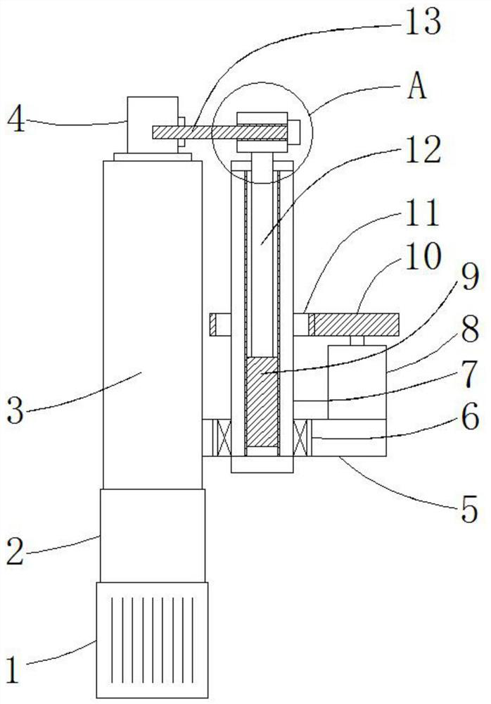
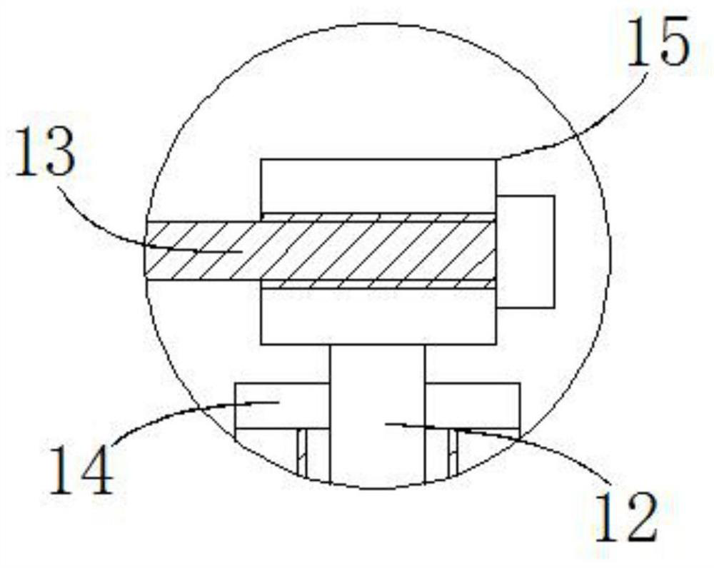
[0017] refer to Figure 1-2 , a new type of electro-hydraulic push rod, including a motor 1, the top of the motor 1 is welded with a hydraulic cylinder 2, the top of the hydraulic cylinder 2 is welded with a piston rod 3 with the piston end facing upward, and the piston end of the piston rod 3 is welded with a rectangular The fixed block 4 and the outer ring of the piston rod 3 are vertically welded with a rectangular mounting plate 5, and a circular mounting hole is vertically opened on the mounting plate 5, and a circular rotating tube 7 is sleeved in the mounting hole, and the rotating tube 7 The top end extends out of the mounting plate 5, and the outer ring of t...


PUM


Abstract

The invention discloses a novel electro-hydraulic push rod. The electro-hydraulic push rod comprises a motor, a hydraulic cylinder is welded to the top of the motor, a piston rod with an upward pistonend is welded to the top of the hydraulic cylinder, a rectangular fixing block is welded to the piston end of the piston rod, a rectangular mounting plate is vertically welded to the outer ring of the piston rod, a round mounting hole is vertically formed in the mounting plate, a round rotating tube is connected to the mounting hole in a rotating and sleeving mode, the top end of the rotating tube extends out of the mounting plate, an outer ring, above the mounting plate, of the rotating tube is fixedly sleeved with a gear ring, a driving motor with an output end facing upwards is welded to the top of the mounting plate, a gear is welded to the output end of the driving motor, the gear ring is in meshed connection with the gear, the inner ring of the rotating tube is in threaded and sleeved connection with a threaded column, a rotating rod is welded to the top end of the threaded column, the top end of a rotating rod extends out of the rotating tube, and a threaded sleeve is horizontally welded to the top end of a rotating rod. The electro-hydraulic push rod can still operate continuously when the motor or the hydraulic cylinder are damaged, so that emergency capacity is high.

Description

technical field [0001] The invention relates to the technical field of electro-hydraulic push rod design, in particular to a novel electro-hydraulic push rod. Background technique [0002] The electro-hydraulic push rod is a hydraulically driven manipulator integrating machine, electricity and hydraulics. It is suitable for reciprocating push-pull linear motion, and can also be used in places that need to raise, lower or clamp work objects, and can realize long-distance dangerous areas. Centralized or automatic control. [0003] The existing electro-hydraulic push rod cannot operate after the motor or hydraulic cylinder is damaged, and the emergency response capability is poor. Therefore, it is necessary to design a new type of electro-hydraulic push rod. Contents of the invention [0004] The purpose of the present invention is to solve the problem that the existing electro-hydraulic push rod cannot operate after the motor or the hydraulic cylinder is damaged, and the em...

Claims


Application Information

Patent Timeline
Patent Type & Authority Patents(China)
IPC IPC(8): F15B15/14F15B15/20H02K7/06
CPCF15B15/088F15B15/14F15B15/20H02K7/06
Inventor 葛乃安
Owner 扬州市慧宇科技有限公司
Why Eureka
Try Eureka