Cooling system

A technology for cooling systems and heat exchange components, which is used in household refrigeration devices, lighting and heating equipment, household appliances, etc., can solve the problems of high investment cost and low equipment utilization rate.

Inactive Publication Date: 2018-12-07
BEIJING GOLDWIND SCI & CREATION WINDPOWER EQUIP CO LTD
View PDF0 Cites 5 Cited by
  • Summary
  • Abstract
  • Description
  • Claims
  • Application Information

AI Technical Summary

Problems solved by technology

[0004] The invention solves the problems of low equipment utilization rate and high investment cost of the cooling system of the existing generator set test bench

Method used


Image

  • Cooling system
  • Cooling system
  • Cooling system

Examples


Embodiment Construction

[0020] The technical solutions of the present invention will be clearly and completely described below in conjunction with the accompanying drawings. Apparently, the described embodiments are some of the embodiments of the present invention, but not all of them. Based on the embodiments of the present invention, all other embodiments obtained by persons of ordinary skill in the art without making creative efforts belong to the protection scope of the present invention.

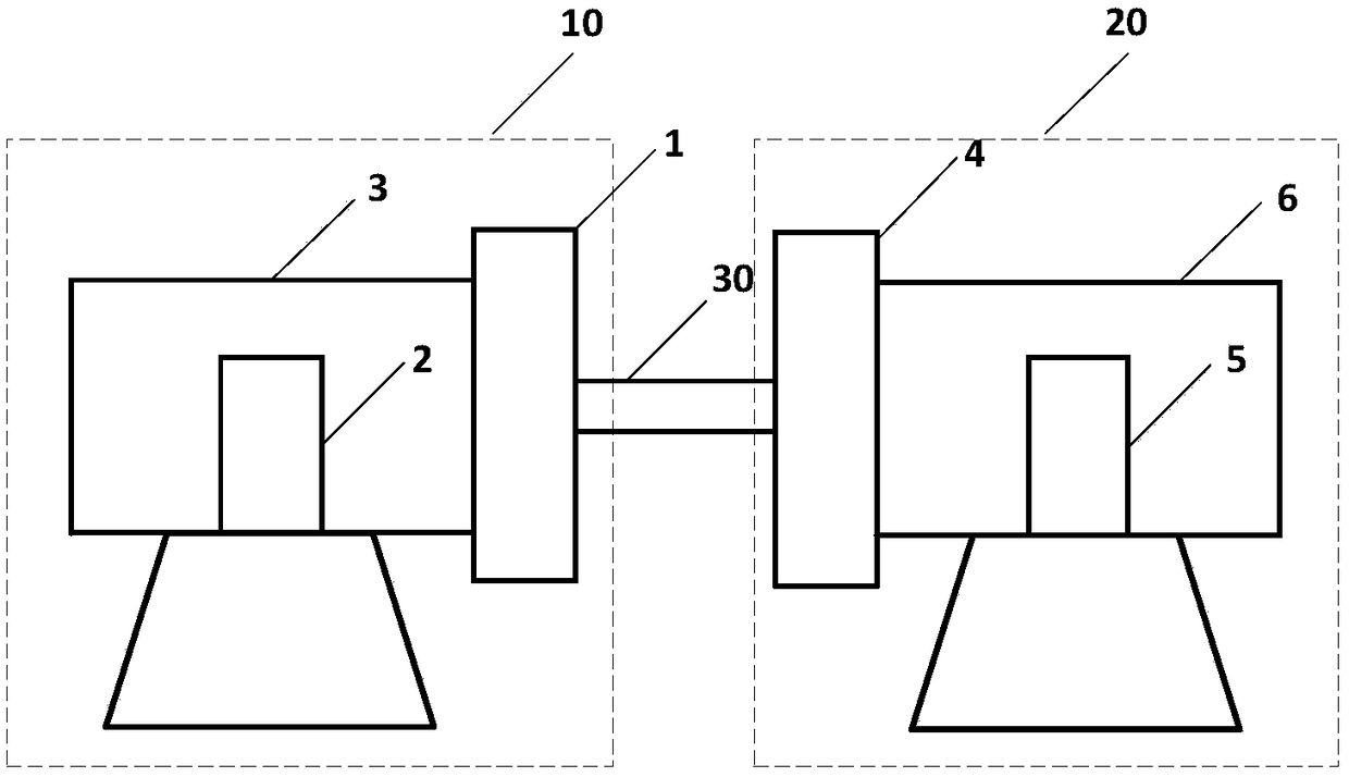
[0021] An embodiment of the present invention provides a cooling system, which is used for cooling various heat-generating components of an experimental test bench for a generating set. Specifically, the generating set may be a wind power generating set. Such as figure 1 As shown, the generator test bench may include: a driving end part 10 , a tested end part 20 and a connecting shaft 30 connecting the driving end part 10 and the tested end part 20 . In this embodiment, the dragging end component 10 may inclu...


PUM


Abstract

The invention discloses a cooling system for cooling multiple heat generation parts. The cooling system comprises multiple first heat exchange modules connected in parallel for heat exchange with eachheating part, and a second heat exchange module for heat exchange with the first heat exchange modules and external environments to integrate the cooling system of the multiple heat generation parts;the initial investment of equipment is reduced, and the operation cost is saved; the overall planning of an experimental center is convenient; the space and land sources are saved; first heat exchange quantities of all the first heat exchange modules are metered through a heat metering module to obtain heat generation quantities of the heating parts corresponding to the first heat exchange modules; and the second heat exchange module can adjust the working state through the heat generation quantity of each heating part, so that each heat generation part can be cooled more precisely, and the normal operation of each heat generation part can be guaranteed.

Description

technical field [0001] The invention relates to the technical field of power generation, in particular to a cooling system. Background technique [0002] With the increasing capacity of a single unit of generating sets, the environment for unit assembly is becoming increasingly harsh, and the thermal problems of the complete unit, subsystems, and sub-components have become a huge challenge for the design and operation of the unit. Taking the wind power generation unit as an example, in terms of unit capacity, it has developed to a higher capacity level of 8MW and 10MW, and the heat production of the unit itself has reached hundreds of KW or MW levels. With the increase of stand-alone capacity, the heat generation corresponding to the subsystems of the unit and the whole machine has increased sharply. How to ensure the temperature indicators of the corresponding subsystems and sub-components of the product has become the key to the design. [0003] At the beginning of produc...

Claims


Application Information

Patent Timeline
Patent Type & Authority Applications(China)
IPC IPC(8): F25D31/00
CPCF25D31/00
Inventor 高杨彭云马盛骏
Owner BEIJING GOLDWIND SCI & CREATION WINDPOWER EQUIP CO LTD
Why Eureka
Try Eureka