
Microchannel gas-liquid separation evaporator device based on distribution recovery channel

A gas-liquid separation and evaporator technology, used in electrical components, indirect heat exchangers, electrical equipment structural parts, etc., can solve the problems of poor heat exchange performance, easy to dry out, uneven liquid replenishment, etc., to ensure sufficient liquid replenishment. , to avoid the effect of local drying

Active Publication Date: 2020-03-17
SHANGHAI JIAO TONG UNIV
View PDF6 Cites 0 Cited by
  • Summary
  • Abstract
  • Description
  • Claims
  • Application Information

AI Technical Summary

Problems solved by technology

[0004] In the traditional microchannel gas-liquid separation evaporator, the working fluid enters directly from one side of the evaporator and flows out from the outlet on the other side. The gas is separated at the outlet, and the heat transfer performance is poor

Method used


Image

  • Microchannel gas-liquid separation evaporator device based on distribution recovery channel
  • Microchannel gas-liquid separation evaporator device based on distribution recovery channel
  • Microchannel gas-liquid separation evaporator device based on distribution recovery channel

Examples


Embodiment Construction

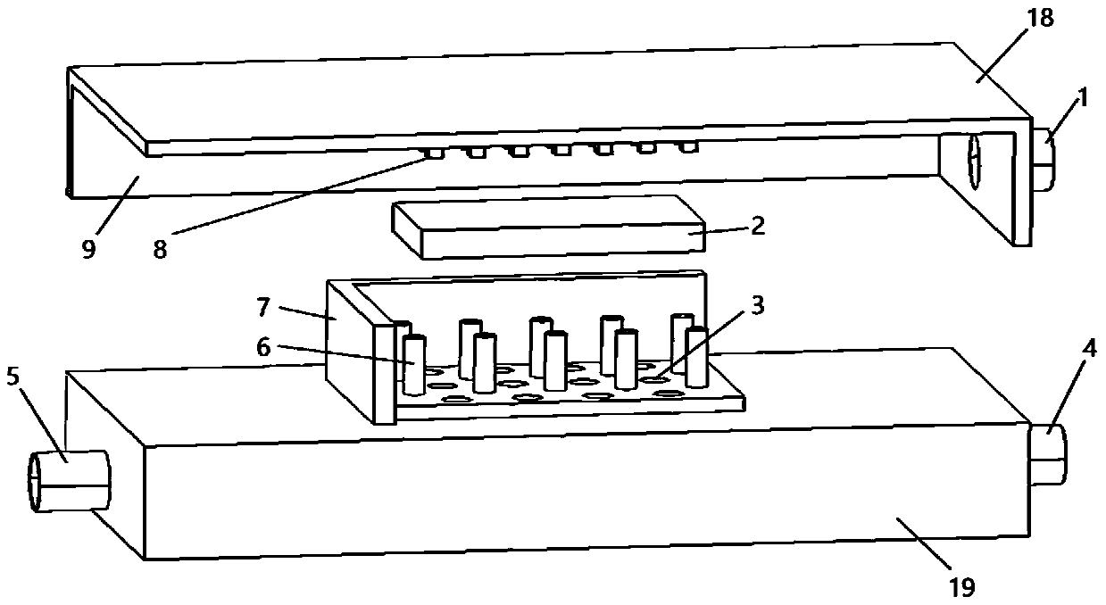
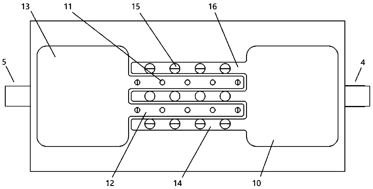
[0024] Such as figure 1 As shown, it is a gas-liquid separation evaporator device involved in this embodiment, comprising: a microchannel structure 9 and a distribution and recovery structure 19, the microchannel structure 9 is provided with a gas phase outlet 1, and the distribution and recovery structure 19 is respectively provided with a working The mass inlet 5 and the liquid phase outlet 4, wherein: the microchannel structure 9 and the distribution and recovery structure 19 are separated by a wire mesh 2.

[0025] The microchannel structure 9 includes: a heating base 18, pin ribs 8 and a sintering surface 17, wherein: the pin ribs 8 are arranged in an array on the heating base 18, the sintering surface 17 covers the pin ribs 8 and the heating base 18, and the gas phase The outlet 1 is located on the side of the microchannel structure 9 .

[0026] The tops of the pin ribs 8 are connected to the wire mesh 2 .

[0027] The heating base 18 and the pin fins 8 are preferably ...


PUM


Abstract

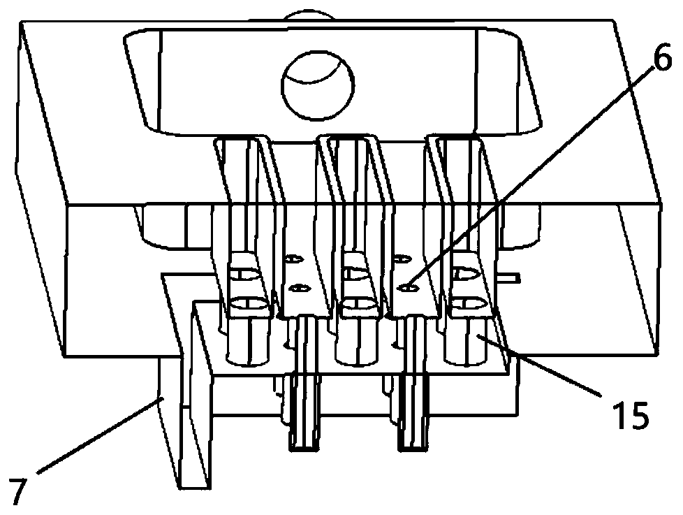
The invention discloses a gas-liquid separation evaporator device. The gas-liquid separation evaporator device comprises a microchannel and a recycling channel. A microchannel structure is provided with a gas phase outlet, and the recycling channel is provided with a working medium inlet and a liquid phase outlet. The microchannel is partitioned from the recycling channel through a wire mesh. Themicrochannel comprises a heating substrate, pin ribs and a sintering surface. The recycling channel comprises a distribution cavity, a flow gathering unit and a backflow cavity. The flow gathering unit comprises liquid supplement nozzles, a distribution channel, backflow holes and a recycling channel. According to the gas-liquid separation evaporator device, liquid supplement and excessive liquidrecycling are conducted through a distribution and recycling structure; by means of a porous sintering structure, it is guaranteed that all areas on a heat exchange face are in the wet state; thin liquid film evaporation occurs on the surface, and two-phase flow in the cavities is similar to annular flow; the device is provided with a gas phase working medium outlet and the liquid phase working medium outlet, a gas phase working medium enters a condenser or a liquid storage tank for cooling, and a liquid phase working medium enters a next evaporator for continuous heat exchange; and series connection efficient cooling of multiple heat-emitting elements is achieved.

Description

technical field [0001] The invention relates to a technology in the technical field of enhanced heat exchange, in particular to a microchannel gas-liquid separation evaporator device based on a distribution recovery channel. Background technique [0002] The rapid development of electronic circuits makes it difficult for traditional air-cooled cooling technology to meet the heat transfer requirements of electronic components. More effective liquid cooling technology is needed to dissipate heat and cool electronic components. In the liquid cooling heat dissipation technology, the micro-channel evaporator has a more significant effect of heat dissipation and cooling on the micro-scale heat exchange surface due to its small structural size and large surface area. [0003] In practical applications, there are often multiple heating elements on a single circuit board. In order to ensure that each evaporator has sufficient heat exchange capacity, the evaporator is usually separate...

Claims


Application Information

Patent Timeline
Patent Type & Authority Patents(China)
IPC IPC(8): F28D15/02F28F17/00H05K7/20
CPCF28D15/02F28D2015/0225F28F17/005F28F2260/02H05K7/20336
Inventor 洪芳军崔付龙袁璐凌李健
Owner SHANGHAI JIAO TONG UNIV
Learn More