
Phase change energy storage element

A technology of phase change energy storage and components, applied in heat storage equipment, lighting and heating equipment, heat exchanger shells, etc., can solve the problems of phase change material leakage and heat exchange efficiency, so as to ensure heat exchange efficiency and improve heat exchange Efficiency, effect of large dimensional stability

Pending Publication Date: 2018-12-07
凡则(上海)节能环保科技有限公司
View PDF10 Cites 0 Cited by
  • Summary
  • Abstract
  • Description
  • Claims
  • Application Information

AI Technical Summary

Problems solved by technology

[0007] In order to solve the problems of phase change material leakage and low heat exchange efficiency in existing heat storage elements, the purpose of the present invention is to provide a phase change energy storage element

Method used


Image

  • Phase change energy storage element
  • Phase change energy storage element
  • Phase change energy storage element

Examples


Embodiment 1

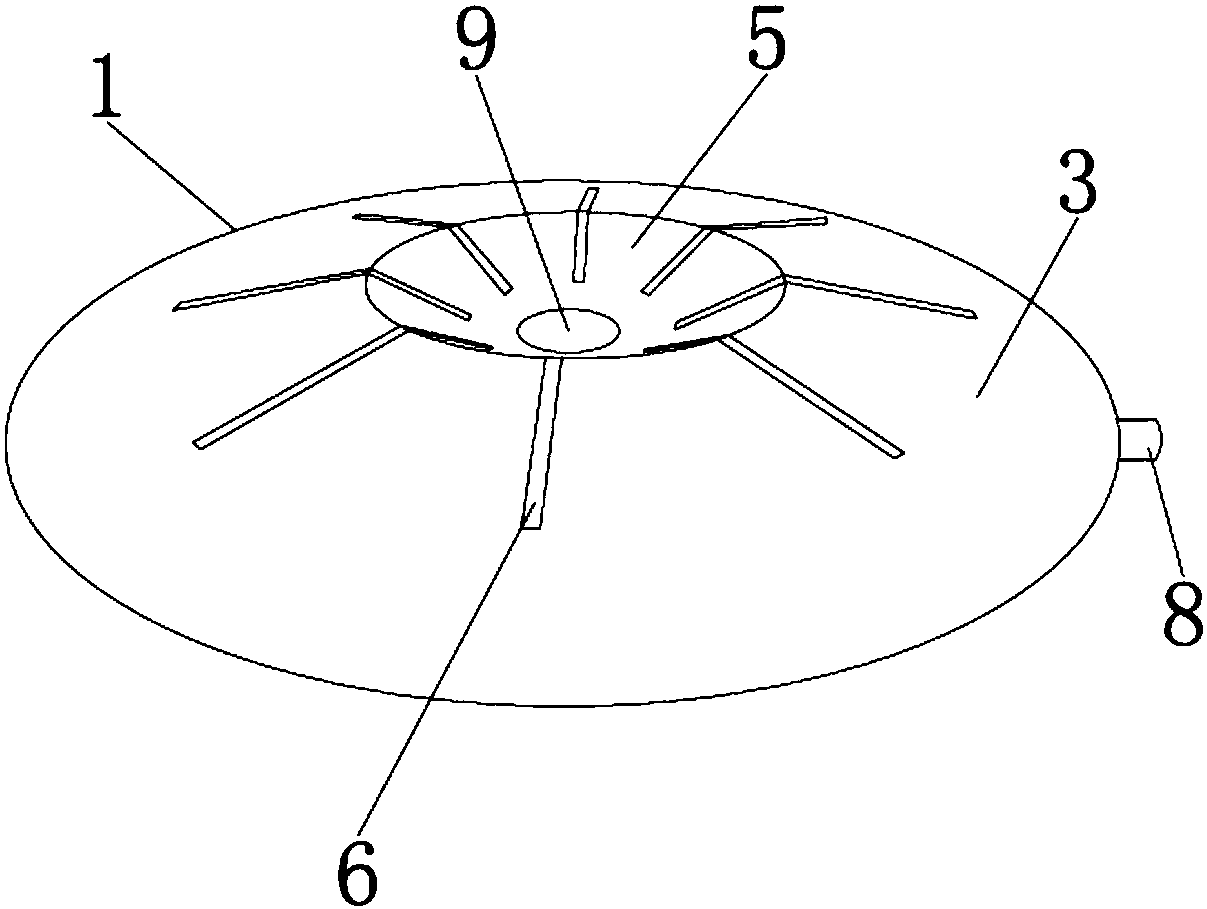
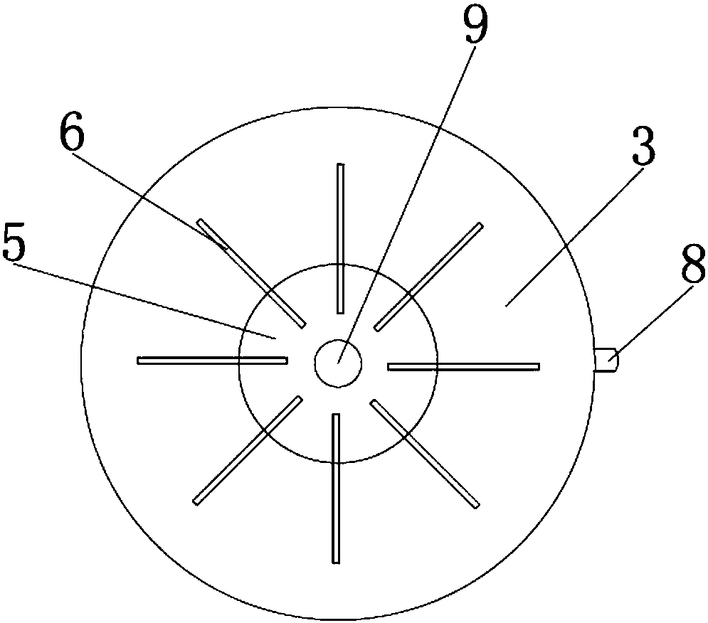
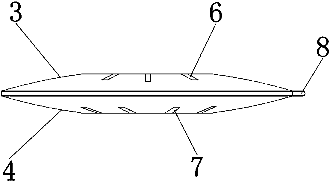
[0037] Such as figure 1 , 2 , 3, 4, 5, the phase change energy storage element is a closed system surrounded by a plastic shell 1, the shell 1 is preferably thermoplastic, more preferably polyethylene, polypropylene, polyamide or polycarbonate, the shell 1 The top view shape of the shell is circular, elliptical or rectangular, and the shape of the shell 1 is similar to that of a convex lens, with a thick center and a thin edge.

[0038] The housing 1 includes a top surface 3 and a bottom surface 4, which are arranged symmetrically, and the top surface 3 and the bottom surface 4 are respectively curved surfaces protruding outward. The top surface 3 is provided with a first central depression 5, and eight first grooves 6 are arranged around the first central depression 5, and one end of the first groove 6 extends into the first central depression 5, adjacent to the first depression. The included angle of the groove 6 is 45°, which ensures the contact area and uniformity betwee...

Embodiment 2

[0043] The difference from Embodiment 1 is that the phase-change energy storage element does not include through holes, and when the phase-change energy storage element is in contact with the heat-conducting medium, the heat-conducting medium is located on the outer surface of the phase-change energy storage element.


PUM

PropertyMeasurementUnit
Angleaaaaaaaaaa
Maximum widthaaaaaaaaaa
Thicknessaaaaaaaaaa

Abstract

The invention discloses a phase change energy storage element. A closed system is defined by a plastic shell, the shell comprises a top surface and a bottom surface, the top surface is provided with afirst central recessed area, a plurality of first grooves are formed around the first central recessed area, one ends of the first grooves extend into the first central recessed area, a second central recessed area is arranged at the position, corresponding to the first central recessed area, of the bottom surface, a plurality of second grooves are formed around the second central recessed area,one ends of the second grooves extend into the second central recessed area, a feeding port is formed on one side of the shell, and the feeding port is used for injecting a phase change material. According to the phase change energy storage element, the shell of a special structure is adopted, so that quite large size stability is achieved.

Description

technical field [0001] The invention relates to the technical field of energy storage elements, in particular to a phase change energy storage element. Background technique [0002] Inorganic phase change material is a substance that changes shape due to temperature changes and can provide latent heat. The process of inorganic phase change materials changing from solid to liquid or from liquid to solid is called a phase change process. At this time, the phase change material will absorb or release a large amount of heat. The phase change energy storage element is formed by filling the inorganic phase change material into a container, but the heat transfer efficiency of the existing phase change energy storage element is not high. [0003] Publication number CN 102538532A discloses "a phase change energy storage element", which includes a stainless steel cylinder, one end of the stainless steel cylinder is provided with a feed port, an end cover is provided on the feed port,...

Claims


Application Information

Patent Timeline
IPC IPC(8): F28D20/02F28F9/00F28F13/00F28F21/06
CPCF28D20/021F28F9/00F28F13/00F28F21/06F28F2265/16Y02E60/14
Inventor 胡建民陈大平薛祝亮
Owner 凡则(上海)节能环保科技有限公司
Learn More