A device and method for simulating the stress on the lining support structure of the annular tunnel fluid filling
A supporting structure and fluid technology, which is applied in the fields of mining cavern support, engineering tunnels, and engineering roadways, can solve the problems that the force cannot be recorded well, the simulation device is large in size, and the tunnel cannot be simulated, etc., and achieves extensive engineering practice significance and application prospects, simple device structure, and convenient operation
- Summary
- Abstract
- Description
- Claims
- Application Information
AI Technical Summary
Problems solved by technology
Method used
Image
Examples
Embodiment 1
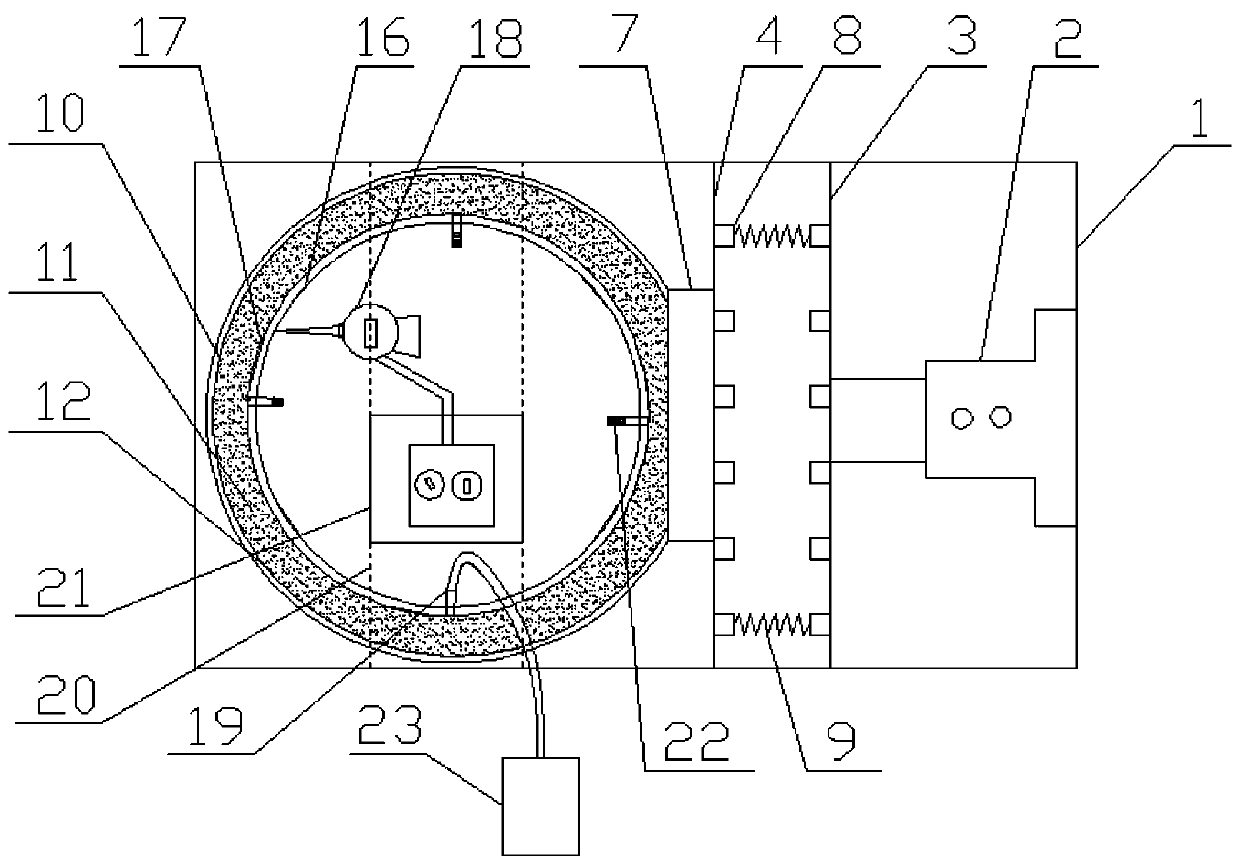
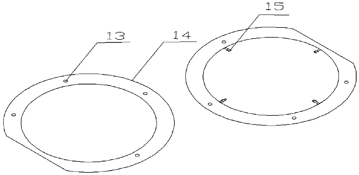
[0039] Such as Figure 1-4 As shown, a device for simulating the stress of the annular tunnel fluid filling lining support structure is characterized in that it includes a prefabricated reaction force frame 1, and a chute 5 is processed on the inner side wall of the prefabricated reaction force frame 1. The first force plate 3 and the second force plate 4 are installed in sliding fit on the chute 5, and the magnetic table displacement meter 18 is installed on the prefabricated reaction force frame 1 through the placement structure of the magnetic table displacement meter. A jack 2 is arranged between the force plate 3 and the prefabricated reaction force frame 1, a plurality of springs 9 are evenly distributed between the first force plate 3 and the second force plate 4, and outside the second force plate 4 The end face is fixed with a raised loading plate 7, the surface of the raised loading plate 7 is pasted with a pressure sensor 17, and the raised loading surface of the ra...
Embodiment 2
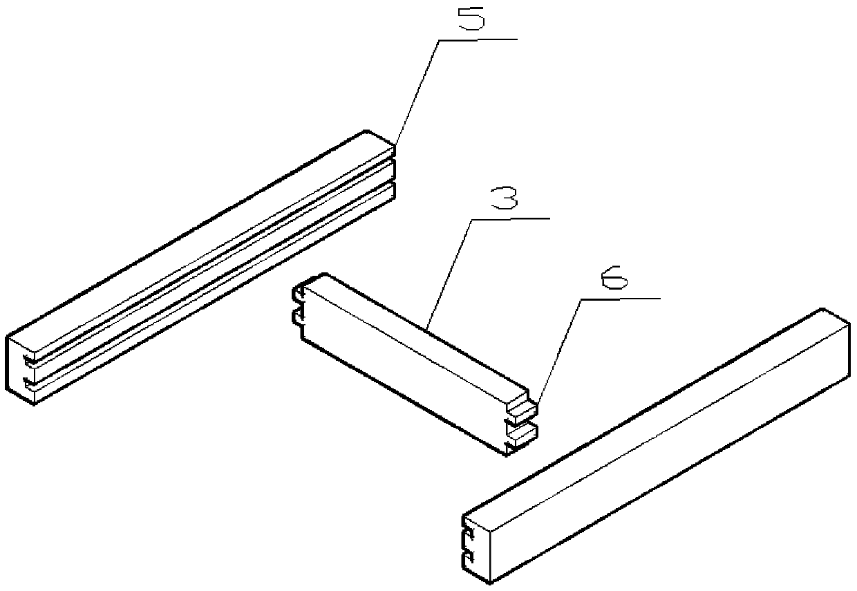
[0048] The reaction force frame 1 is welded by steel plates with greater rigidity and strength, and there are recessed chute 5 on both sides of the prefabricated reaction force frame 1, and the magnetic table displacement meter placement structure is welded on the reaction force frame 1, said The structure is composed of two steel bars with a certain distance welded on the reaction force frame 1 and a steel plate 21 welded in the middle of the thin steel bar 20 .
[0049] Further, the jack 2 is a force-loading device for the device to simulate the load of the tunnel, the bottom of which acts on the reaction frame 1, and the top acts on the first force plate 3 to apply load to the device.
[0050] Further, the first stress plate 3 is made of a steel plate with relatively high rigidity and strength, and the structures at both ends of the first stress plate 3 are protruding convex sliding strips 6, which can be just opposite to the reaction force frame 1. The chute 5 recessed in ...
Embodiment 3
[0061] Any one of the methods for simulating the force-bearing device of the annular tunnel fluid-filled lining support structure to carry out the simulation test, the device applies a load through the jack 2 to act on the first force-bearing plate 3 and the second force-bearing plate 4, and the force-bearing The plate further acts the load on the separated circular steel pipe 14. When the load reaches 85% of the yield limit of the steel pipe, the pressure relief stage is performed. In the pressure relief stage, the rubber piston 22 at the end of the pressure relief conduit 19 is removed, and the suction The catheter of the equipment 23 is inserted into the pressure relief port 13 for sand discharge treatment. After the pressure relief is completed, the pressure relief port 13 is sealed with a rubber piston 22 to ensure that the filling does not flow out during the loading stage, and then the loading and unloading operation is performed. During this process The mechanical param...
PUM
 Abstract
Description
Claims
Application Information
 - R&D
- Intellectual Property
- Life Sciences
- Materials
- Tech Scout
- Unparalleled Data Quality
- Higher Quality Content
- 60% Fewer Hallucinations
Browse by: Latest US Patents, China's latest patents, Technical Efficacy Thesaurus, Application Domain, Technology Topic, Popular Technical Reports.
© 2025 PatSnap. All rights reserved.Legal|Privacy policy|Modern Slavery Act Transparency Statement|Sitemap|About US| Contact US: help@patsnap.com


