Calibration method and device for error of included angle between ccd target face and mounting and positioning face based on leaked radiation imaging

A technology of installation positioning and radiation imaging, applied in the field of optical calibration, can solve the problems of difficult to ensure the accuracy of the instrument, difficult to distinguish, low accuracy, etc., to achieve the effect of improving detection contrast and accuracy, convenient detection and high accuracy

Pending Publication Date: 2018-12-07
NANJING UNIV OF SCI & TECH
View PDF0 Cites 5 Cited by
  • Summary
  • Abstract
  • Description
  • Claims
  • Application Information

AI Technical Summary

Problems solved by technology

Most of the existing methods for detecting the angle between the ccd target surface and the mechanical installation surface are non-contact optical measurement methods and focal plane measurement methods. The main problems are: (1) low accuracy
Due to the mechanical packaging of the target surface, there are many protective media within the range of the working surface, and the position of the ccd target surface needs to be directly observed with the naked eye and compared with a micrometer, and there are small errors that are difficult to adjust
(2) Difficult to distinguish
This not only adds an additional process, but also makes it difficult to ensure that the instrument remains accurate during long-term use.

Method used


Image

  • Calibration method and device for error of included angle between ccd target face and mounting and positioning face based on leaked radiation imaging
  • Calibration method and device for error of included angle between ccd target face and mounting and positioning face based on leaked radiation imaging
  • Calibration method and device for error of included angle between ccd target face and mounting and positioning face based on leaked radiation imaging

Examples


Embodiment Construction

[0029] The present invention will be further described below with reference to the accompanying drawings.

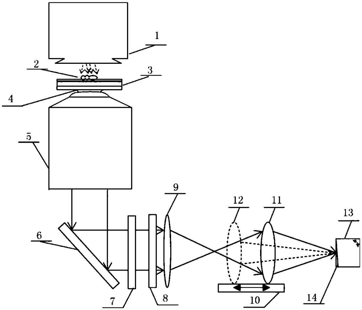
[0030] combine figure 1 , a calibration device based on the angle error between the CCD target surface and the installation positioning surface based on leaked radiation imaging, the device includes an illumination light source 1, a fluorescent substance to be measured 2, a metal layer-containing chip substrate 3, a refractive index matching oil 4, a display Micro-objective lens 5, reflective mirror 6, polarizing element group 7, filter 8, condenser lens 9, horizontal moving axis 10, imaging lens 11 and ccd image sensor 13, the illumination light source 1, the metal layer-containing chip substrate 3, The refractive index matching oil 4 and the microscope objective lens 5 are arranged coaxially in sequence, the polarizing element group 7, the filter 8, the condenser lens 9, the imaging lens 11 and the ccd image sensor 13 are arranged coaxially in sequence, and the fluores...


PUM

PropertyMeasurementUnit
thicknessaaaaaaaaaa
thicknessaaaaaaaaaa
wavelengthaaaaaaaaaa

Abstract

The invention discloses a calibration method and device for an error of an included angle between a ccd target face and a mounting and positioning face based on leaked radiation imaging. The device comprises an illuminating light source, a to-be-detected fluorescent material, a metal layer-containing chip substrate, refractive index matching oil, a microobjective, a reflector, a polarization element group, an optical filter, a bunching lens, a horizontal slide rail, an imaging lens and a ccd image sensor. A fluorescent sample irradiated by illuminating light generates a fluorescent surface plasmon wave and leaks radiation through the metal layer-containing chip substrate, and fluorescent imaging is achieved after a signal is collected through the microobjective. In the period, the excitinglight sent by the illuminating light source is filtered by the polarization element group and the optical filter. By moving the position of the imaging lens, the target face of the ccd image sensor is detected by means of leaked radiation Hough transform algorithm, so that the error of the included angle, which is hardly found, between the ccd target face and the mounting and positioning face bymeans of a conventional means is calibrated precisely. The device is simple in structure and high in applicability.

Description

technical field [0001] The invention relates to the technical field of optical calibration, in particular to a method and device for calibrating the angle error between a CCD target surface and an installation positioning surface based on leaked radiation imaging. Background technique [0002] In microscopic imaging, due to technological innovation and the rapid development of new imaging methods, the self-expansion of open optical paths is getting better and better, and commercial microscopes are often accompanied by a combination of multiple imaging methods. However, while ensuring the improvement of imaging resolution and speed, the stability of the expandable optical path is also a concern of users. Small errors often have a potential impact on imaging accuracy. At the same time, with the increasing demand for large-size area array CCD image sensors, some newly developed CCD products often have a large angle error between the target surface and the mechanical mounting a...

Claims


Application Information

Patent Timeline
Patent Type & Authority Applications(China)
IPC IPC(8): G01N21/64
CPCG01N21/6402
Inventor 陈漪恺黄学鹍周芊江左苇沈中华
Owner NANJING UNIV OF SCI & TECH
Why Eureka
Try Eureka