
Detection device for photocatalytic degradation of titanium dioxide and detection method thereof

A detection device and titanium dioxide technology, which is applied in the direction of detection of element existence through oxidation, measurement device, chemical method analysis, etc., can solve the problems of complex operation and low nitrogen elution results, and achieve accurate detection results

Pending Publication Date: 2018-12-07
SHANGHAI LANDLEAF BUILDING TECH CO LTD
View PDF6 Cites 0 Cited by
  • Summary
  • Abstract
  • Description
  • Claims
  • Application Information

AI Technical Summary

Problems solved by technology

[0003] The first one, Invention Patent Application No. 201710789026.2, is an evaluation method for the efficiency of semi-flexible pavement to degrade automobile exhaust gas. It uses samples to degrade by simulating the actual exhaust gas conditions, and the method of detecting gas concentration changes by automobile exhaust gas analyzers to characterize TiO 2 The photocatalytic degradation effect needs to be equipped with gas monitoring equipment, and the operation is more complicated
[0004] The second type, invention patent number 201610051195.1, is a method for testing nano-TiO 2 A method for material photocatalytic degradation of automobile exhaust performance, wherein nano-TiO 2 The tested samples of the materials were placed outdoors, and the target ions (NO 3 - with NO 2 - ) concentration changes, because the tested samples are directly placed in the outdoor environment, and the target ions will be washed away by rainwater in rainy days, resulting in TiO 2 Nitrogen elution results are low

Method used


Image

  • Detection device for photocatalytic degradation of titanium dioxide and detection method thereof
  • Detection device for photocatalytic degradation of titanium dioxide and detection method thereof
  • Detection device for photocatalytic degradation of titanium dioxide and detection method thereof

Examples


Embodiment 1

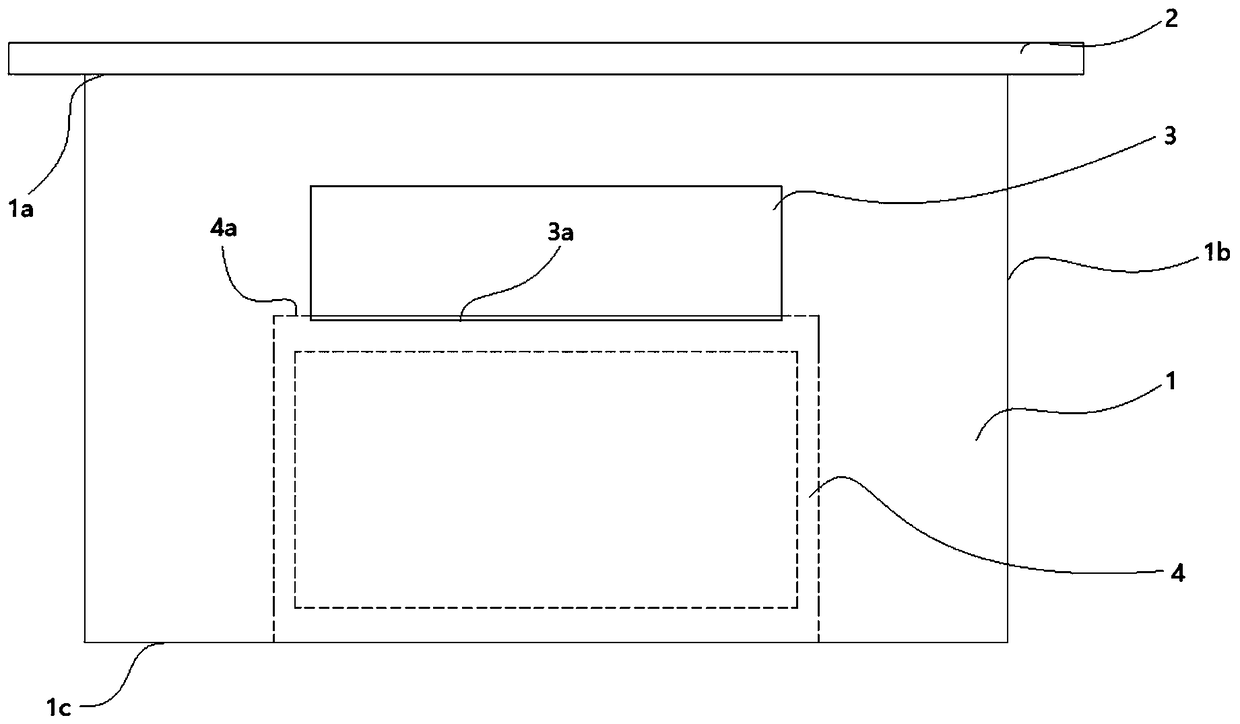
[0034] Such as figure 1 As shown, Embodiment 1 discloses a specific embodiment of a titanium dioxide photocatalytic degradation detection device, including: a hollow shell 1 and a baffle 2, and the hollow shell 1 is provided with a device for taking and placing the tested sample. The access port 5 and the hollow shell 1 are also provided with a vent hole 3 for air circulation, and the vent hole 3 communicates the inside of the hollow shell 1 with the outside of the hollow shell 1 . The baffle plate 2 is arranged at the access opening 5 to cover the access opening 5. In this embodiment, the ventilation hole 3 is a rectangular hole. Of course, in other specific embodiments, it can also be a circular hole or an oval hole. and other arbitrary shapes, which will not be repeated here.

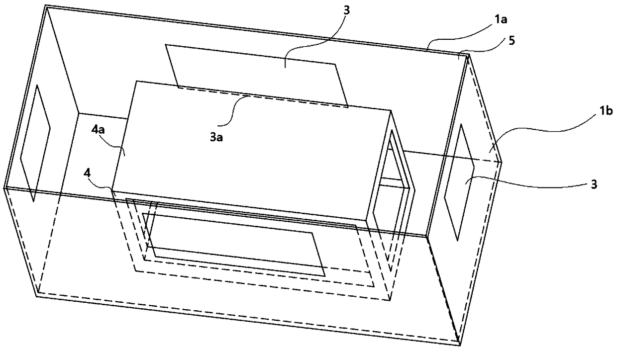
[0035] Specifically, such as figure 2 As shown, the hollow shell 1 is a cuboid, the first end surface 1a of the hollow shell 1 is an open end, and the open end constitutes the access opening 5, an...

Embodiment 2

[0039] Such as figure 1 and figure 2 As shown, embodiment 2 is based on embodiment 1, and the number of vent holes 3 in embodiment 2 is four. As shown in the figure, the connection end surface 1b is divided into four surfaces, each surface is provided with a vent hole 3, and the heights of the four vent holes 3 are all equal. Setting a plurality of ventilation holes 3 can improve the air circulation between the inside and the outside of the hollow shell 1, so that the tested sample is in better contact with the air, so that the elution amount of nitrogen of the tested sample is closer to that of the actual nitrogen. Elution volume.

[0040] better, such as figure 2 As shown, the hollow shell 1 is also provided with a placement bracket 4 for supporting the tested sample. The tested sample is placed on the placement surface 4a of the placed bracket 4, and the vent hole 3 is a rectangular hole. When the tested sample When the sample is placed on the placement surface 4a, the ...

Embodiment 3

[0042] Such as figure 1 and figure 2 As shown, embodiment 3 discloses a detection method, the application of any titanium dioxide photocatalytic degradation detection device in embodiments 1 to 2, specifically includes the following steps:

[0043] S1: Apply the nano-titanium dioxide material evenly on the brick to obtain the tested sample. In this embodiment, only the nano-titanium dioxide material is evenly coated on one side of the brick. In other specific embodiments, it can also be coated The two sides, three sides, etc. of the bricks will not be repeated here;

[0044] S2: Place the sample to be tested inside the hollow shell 1 so that the side coated with the nano-titanium dioxide material faces up, and place the sample to be tested together with the hollow shell 1 at the testing site;

[0045] S3: Take out the tested sample from the hollow shell 1 after the preset time has elapsed. The preset time can be any value from 14 to 40 days, which is determined according to...


PUM


Abstract

The invention discloses a detection device for photocatalytic degradation of titanium dioxide. The detection device comprises a hollow shell and a baffle, wherein a fetching port for fetching a detected sample is formed in the hollow shell; at least one vent hole is formed in the hollow shell; the baffle is arranged on the fetching port and is used for covering the fetching port. A detection method comprises the following steps: uniformly coating a nanometer titanium dioxide material on a brick, thereby acquiring the detected sample, and then placing the detected sample into the hollow shell,wherein the hollow shell is placed on a detection site; 14-40 days later, taking out of the hollow shell; respectively soaking the detected sample into a first scrubbing solution and a second scrubbing solution for 0.5-2h, recording corresponding data and calculating degradation efficiency of the detected sample according to the corresponding data, wherein the first scrubbing solution and the second scrubbing solution are both deionized water. The detection device disclosed by the invention has a simple structure, is low in manufacturing cost, is capable of reducing the influence of rainwateron the detection result for the exhaust gas of titanium dioxide degradation and is capable of acquiring a more accurate detection result.

Description

technical field [0001] The invention relates to the technical field of detection of titanium dioxide degraded automobile exhaust, in particular to a detection device and a detection method for the photocatalytic degradation of titanium dioxide. Background technique [0002] Existing for the detection of TiO 2 There are two methods for photocatalytic degradation of automobile exhaust: [0003] The first one, Invention Patent Application No. 201710789026.2, is an evaluation method for the efficiency of semi-flexible pavement to degrade automobile exhaust gas. It uses samples to degrade by simulating the actual exhaust gas conditions, and the method of detecting gas concentration changes by automobile exhaust gas analyzers to characterize TiO 2 The photocatalytic degradation effect needs to be equipped with gas monitoring equipment, and the operation is more complicated. [0004] The second type, invention patent number 201610051195.1, is a method for testing nano-TiO 2 A me...

Claims


Application Information

Patent Timeline
Patent Type & Authority Applications(China)
IPC IPC(8): G01N31/00
CPCG01N31/005
Inventor 陈军杨向妮
Owner SHANGHAI LANDLEAF BUILDING TECH CO LTD
Learn More