A heat dissipation architecture applied to storage 2u models

A technology of machine type and air guide frame, which is used in instruments, computing, electrical and digital data processing, etc., can solve the problem of high temperature of the rear hard disk, and achieve the effects of reducing processing accuracy, reducing air intake, and good reliability.

Active Publication Date: 2021-09-28
ZHENGZHOU YUNHAI INFORMATION TECH CO LTD
View PDF4 Cites 0 Cited by
  • Summary
  • Abstract
  • Description
  • Claims
  • Application Information

AI Technical Summary

Problems solved by technology

[0004] The purpose of the present invention is to solve the problem of high temperature of the rear hard disk of the above-mentioned storage 2U model, provide a heat dissipation structure applied to the storage 2U model, make reasonable use of the characteristics of the storage model, and make full use of the limited air volume to meet the The temperature requirements of each device, to achieve the cooling of the rear hard disk

Method used


Image

  • A heat dissipation architecture applied to storage 2u models
  • A heat dissipation architecture applied to storage 2u models
  • A heat dissipation architecture applied to storage 2u models

Examples


Embodiment 1

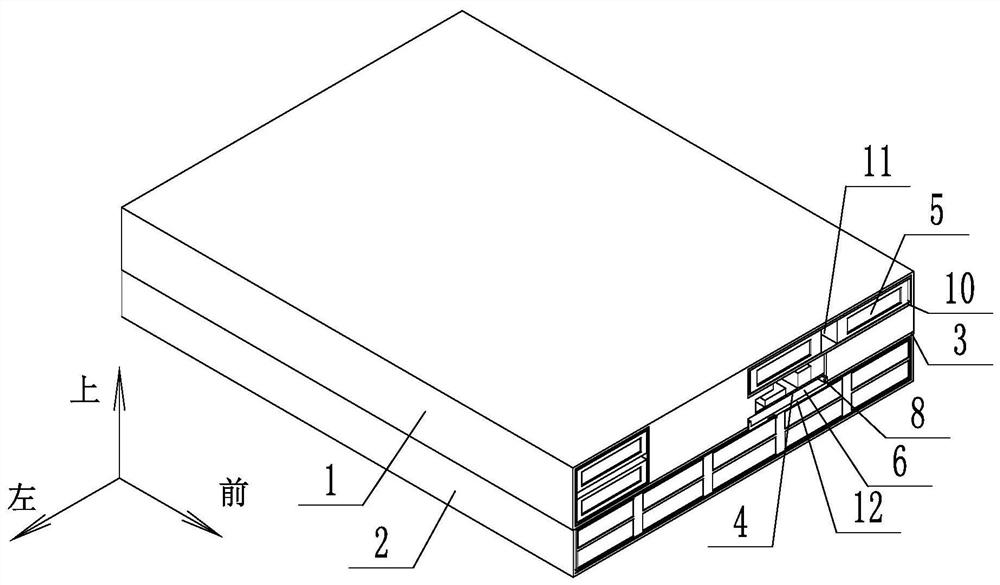
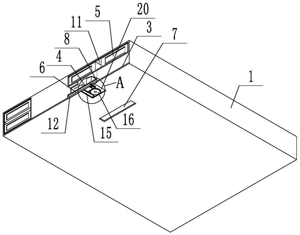
[0038] Such as figure 1 As shown, a heat dissipation architecture applied to a storage 2U model, the storage 2U model includes an upper node 1 and a lower node 2, the upper node 1 is provided with a tray 3, a motherboard 4 and a hard disk 5, and the lower node 2 is provided with multiple The hard disk 5 is arranged in the server through the hard disk bracket 10. It is characterized in that an air duct 6 is provided between the tray 3 and the main board 4, and an opening 7 is provided at the lower end of the tray 3. Corresponding to the hard disk 5, the opening 7 communicates with the air duct 6, the air duct 6 is provided with an air guide frame 8, and the front end of the air guide frame 8 is provided with an arc portion 9, and the arc portion 9 corresponds to the opening 7, and the upper node 1 A gap 11 is provided between the two hard disks 5 in the hard disk bracket 10 . The hard disk bracket 10 is installed in the case, and its installation method is the prior art, so it...

Embodiment 2

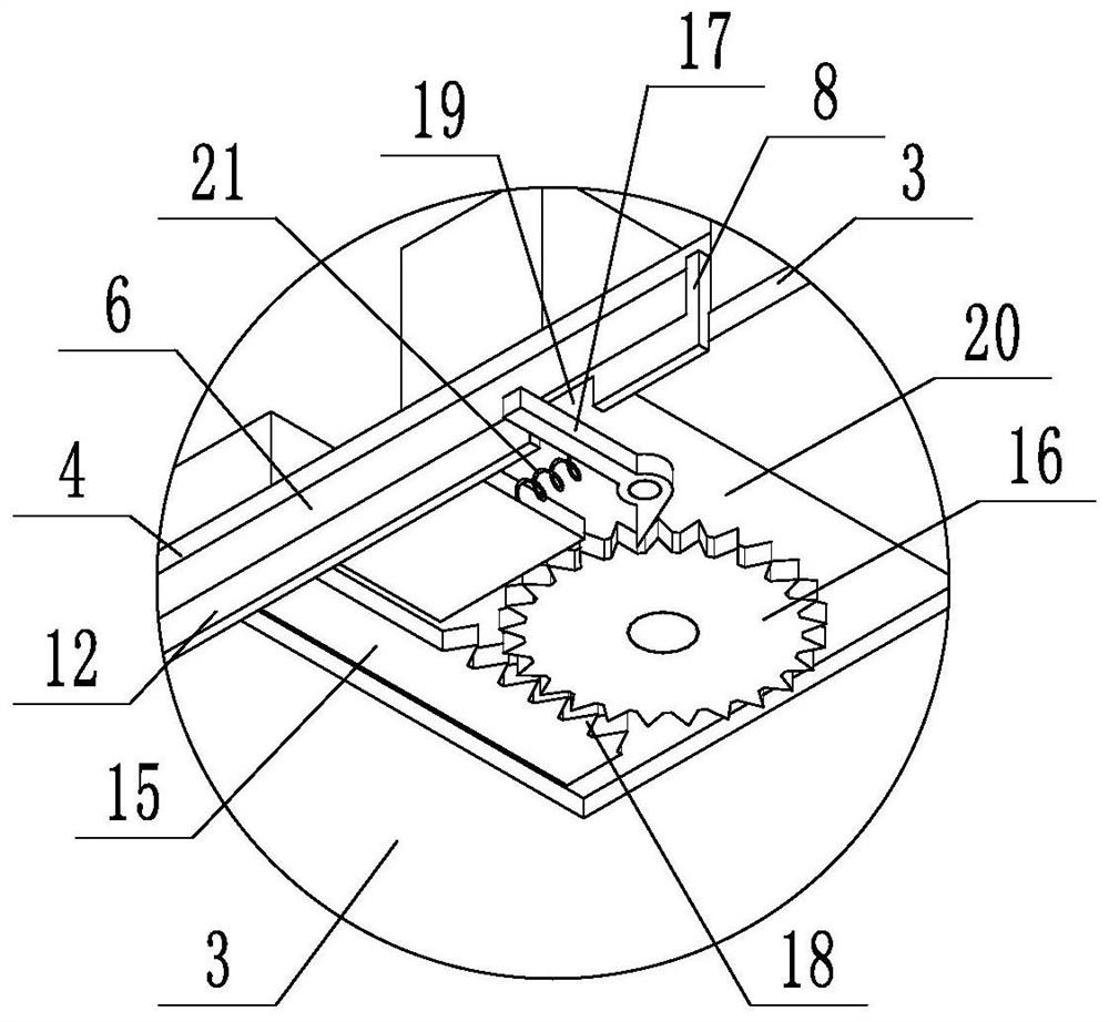
[0052] Such as Figure 10 and Figure 11 As shown, the lower end of the air duct 6 is fully open, so that the air flow in the air duct 6 can blow to the three rows of hard disks in the lower node. The air guide frame 8 and the slideway 28 are locked by the second locking screw 29, the front end of the air guide frame 8 is provided with a second positioning block 30, the rear end of the air duct 6 is provided with a positioning groove 31, and the second positioning block 30 and the positioning groove 31 fits. When installing the air guide frame 8, the air guide frame 8 is inserted deep into the air duct 6 along the positioning groove 31 until the second positioning block 30 matches the positioning groove 31, and then the second locking screw 29 locks the air guide frame 8 and the slide Road 28, the wind guide frame 8 is fixed.

[0053] Such as Figure 12 and Figure 13 As shown, the lower end of the wind guide frame 8 is provided with a third groove 32 , and the second foa...


PUM


Abstract

The invention discloses a heat dissipation structure applied to a storage 2U model. The storage U model includes an upper node and a lower node. The upper node is provided with a tray, a motherboard and a hard disk, and the lower node is provided with multiple rows of hard disks. The hard disk passes through the hard disk. The bracket is installed in the server. An air duct is provided between the tray and the main board. An opening is provided at the lower end of the tray. The opening corresponds to the rear hard disk of the lower node. The opening is connected to the air duct. There is a circular arc at the front end of the air frame, which corresponds to the opening. There is a gap between the two hard drives in the hard drive bracket. The air flow at the front ambient temperature is directed from the opening to the rear hard drive of the lower node through the air guide frame. The gap between the two hard disks makes the air flow directly correspond to the radiator of the rear CPU, which not only ensures the air intake but also reduces the intake air temperature, and the cooling effect is good.

Description

technical field [0001] The invention relates to the technical field of heat dissipation of storage servers, in particular to a heat dissipation architecture applied to storage 2U models. Background technique [0002] With the development of new technologies such as cloud computing and big data, the bandwidth and capacity requirements for data storage are getting higher and higher, and the computing speed and computing power of processors are also increasing. The storage density required in 1U or 2U nodes is constantly increasing. As a result, the temperature of various components such as memory, hard disk, and CPU has also continued to soar. The heat dissipation of electronic devices has become a very burning problem, and the society’s requirements for power consumption are getting higher and higher. Energy saving is currently a main trend. [0003] Now the demand for hard disks in servers is getting higher and higher. How to place more hard disks in a limited space to meet...

Claims


Application Information

Patent Timeline
Patent Type & Authority Patents(China)
IPC IPC(8): G06F1/20
CPCG06F1/20
Inventor 宗斌
Owner ZHENGZHOU YUNHAI INFORMATION TECH CO LTD
Why Eureka
Try Eureka