High current inductance
A technology of high current and inductance, applied in the field of inductance, can solve the problem of slow processing speed of inductance, and achieve the effect of improving processing speed and shortening assembly time.
- Summary
- Abstract
- Description
- Claims
- Application Information
AI Technical Summary
Problems solved by technology
Method used
Image

Examples
Embodiment 1
[0028] figure 1 It is the structure diagram of the inductor in Embodiment 1 of the large current inductor of the present invention.
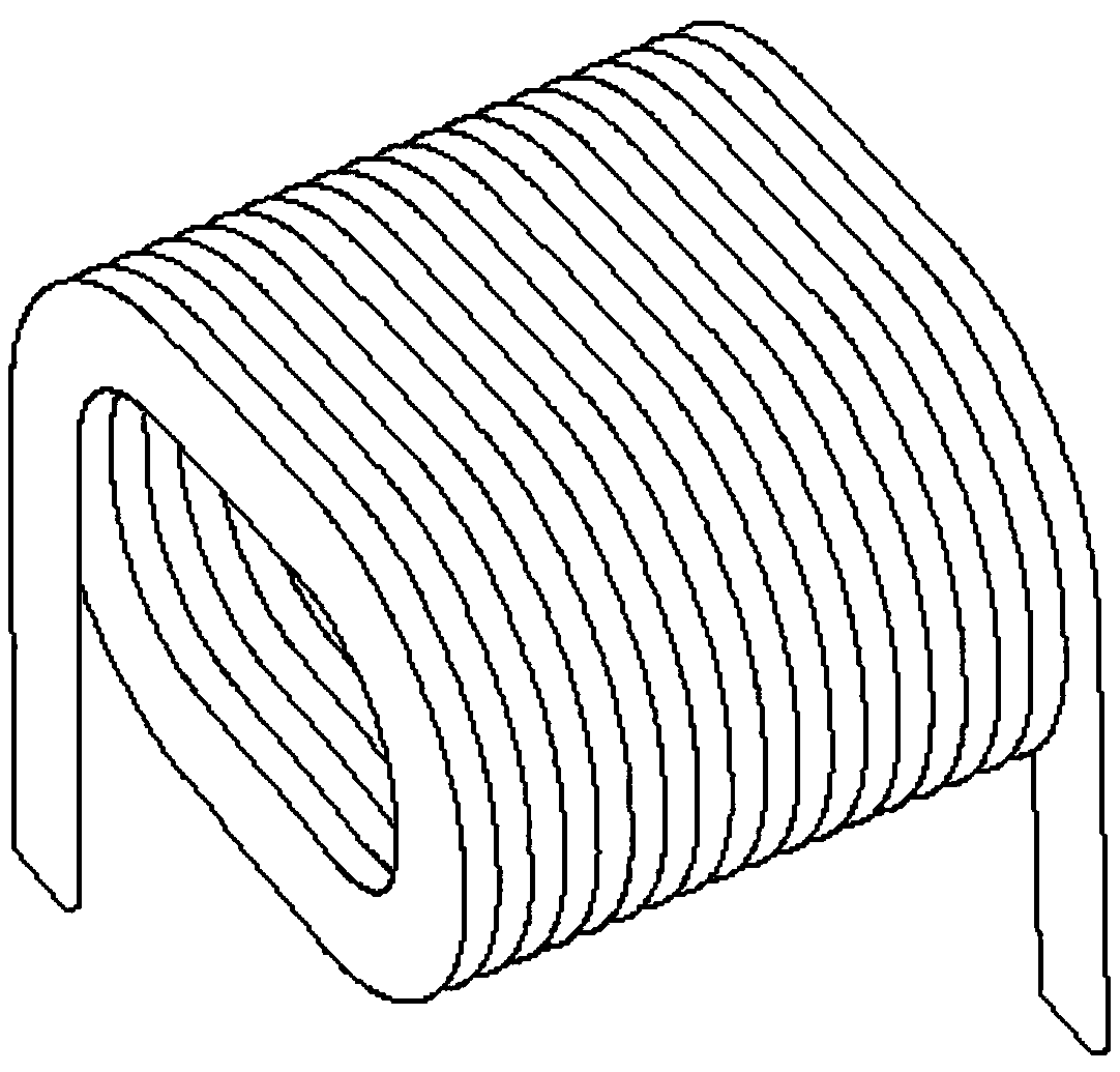
[0029] figure 2 It is a structural diagram of the inductance coil in Embodiment 1 of the large current inductance of the present invention.
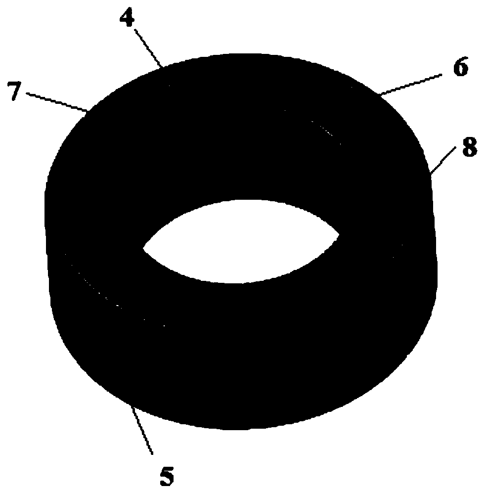
[0030] image 3 It is a structural diagram of the magnetic ring in Embodiment 1 of the large current inductor of the present invention.
[0031] Figure 4 It is a structural diagram of two semicircular magnetic rings in Embodiment 1 of the high-current inductor of the present invention.
[0032] Figure 5 It is an assembly structure diagram of the magnetic ring and the inductance coil in Embodiment 1 of the large current inductor of the present invention.
[0033] Image 6 It is a structural diagram of the fixed base in Embodiment 1 of the high-current inductor of the present invention.
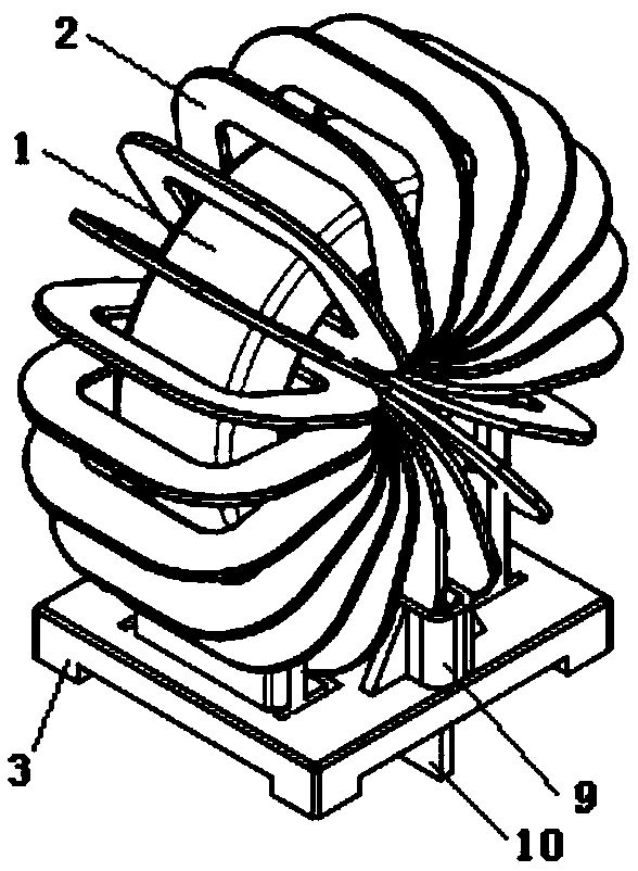
[0034] see Figure 1 to Figure 6 , the high-current inductor includes a magnetic ring set 1 , an inductance c...
Embodiment 2
[0047] Figure 7 It is the structure diagram of the inductor in Embodiment 2 of the large current inductor of the present invention.
[0048] The difference between Embodiment 2 and Embodiment 1 is that the magnetic ring set 1 includes four magnetic rings 4 . The four magnetic rings 4 are arranged in sequence along the axial direction. Due to the increase in the number of magnetic rings 4 , the size of the corresponding inductance coil 2 also increases to match the magnetic ring set 1 . By adjusting the number of the magnetic rings 4, the magnetic rings can satisfy different current inductances.
PUM
 Abstract
Description
Claims
Application Information
PatSnap Eureka turns technology decisions into work you can execute. Powered by our Innovation Knowledge Graph, it runs expert workflows across engineering, life sciences, materials and intellectual property. Get your review-ready output in minutes.


