Shaft voltage reduction structure and plastic packaging motor equipped with shaft voltage reduction structure

A shaft voltage and electrical connection technology, which is applied in structural connection, electrical components, electromechanical devices, etc., can solve problems such as voltage overshoot of the inner and outer rings of the bearing, electric corrosion of the inner and outer rings and balls, breakdown of the oil film of the bearing raceway, etc., to ensure The effect of motor life and reliability, reduction of electric corrosion risk, and wide application of products

Pending Publication Date: 2018-12-07
WOLONG ELECTRIC GRP CO LTD
View PDF5 Cites 5 Cited by
  • Summary
  • Abstract
  • Description
  • Claims
  • Application Information

AI Technical Summary

Problems solved by technology

[0002] In the existing plastic-sealed EC (BLDC) motor, since the stator core is insulated from the front and rear end covers after the stator is plastic-sealed, the shaft voltage is too high due to high-frequency current and unbalanced windings, and the bearing raceway oil film is broken down by the shaft voltage. Galvanic corrosion of the inner and outer rings and balls has always been a key factor affecting the life of the motor
The countermeasures in the existing industry are mainly to weld the front and rear end covers with wires, or to bond the front and rear end covers with conductive tape on the surface of the stator (this method is less reliable), so that the front and rear end covers form an equal potential. The structure cannot eliminate the induced voltage difference between the stator and the end cover, and there is still a voltage difference between the stator and the rotor, so it cannot completely solve the problem of the voltage tolerance of the inner and outer rings of the bearing, and in some cases there is still the problem of electric corrosion of the bearing raceway and balls

Method used


Image

  • Shaft voltage reduction structure and plastic packaging motor equipped with shaft voltage reduction structure
  • Shaft voltage reduction structure and plastic packaging motor equipped with shaft voltage reduction structure
  • Shaft voltage reduction structure and plastic packaging motor equipped with shaft voltage reduction structure

Examples


Embodiment Construction

[0022] The technical solution of the present invention will be further described in detail below in conjunction with the accompanying drawings.

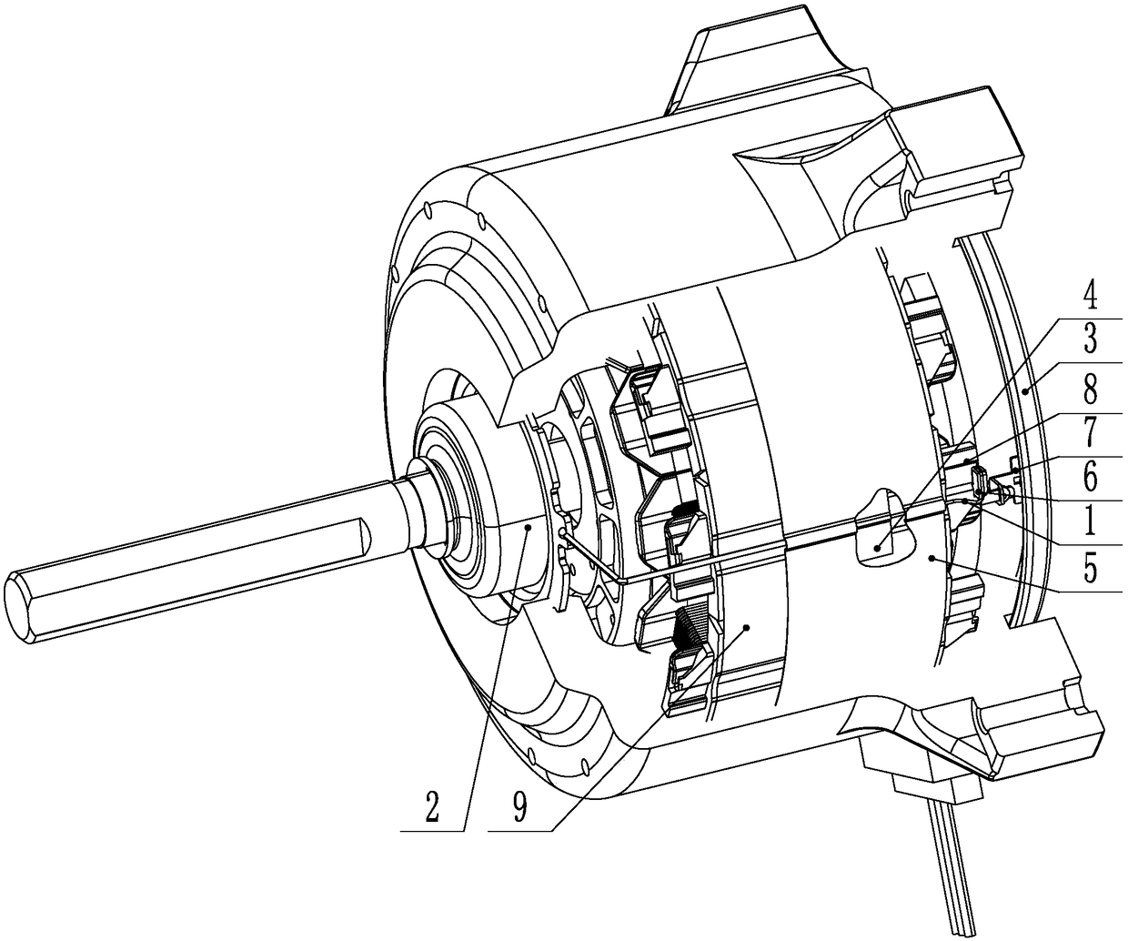
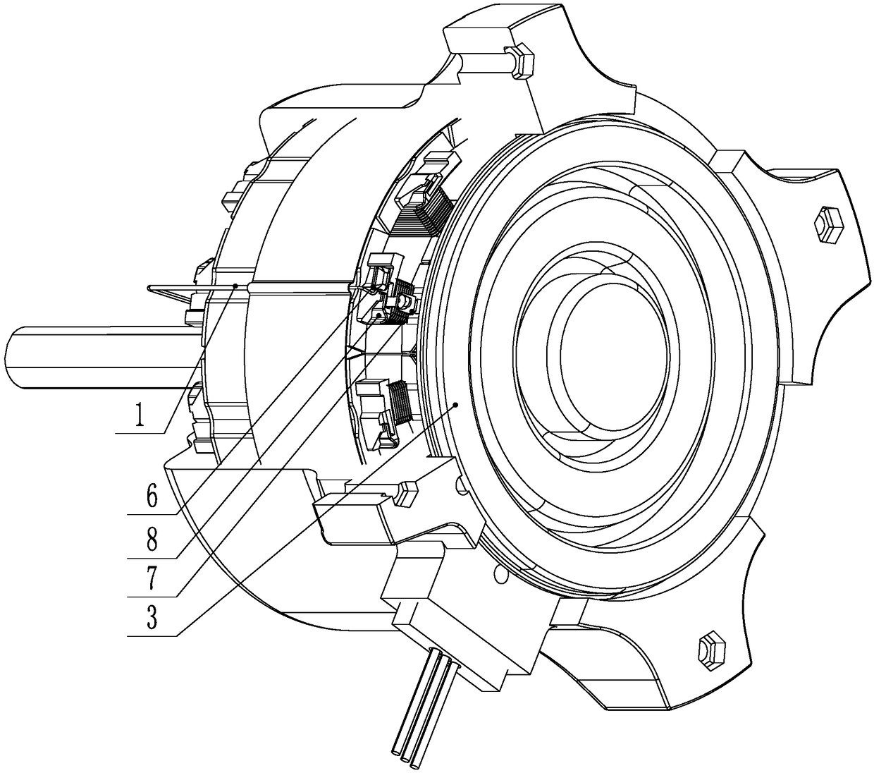
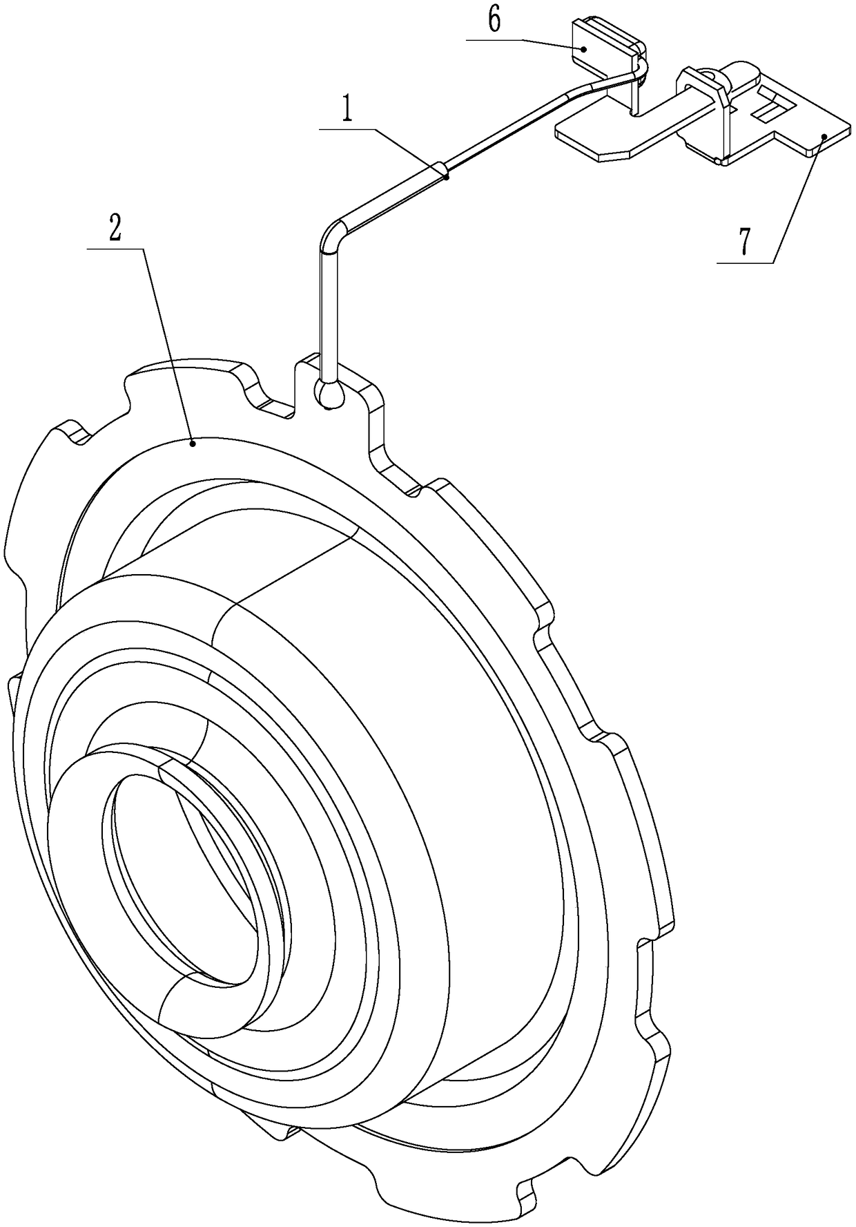
[0023] A structure for reducing shaft voltage, including a wire 1, a stator core electrical connector, and an end cover electrical connector; the first end of the wire 1 is electrically connected to the first end cover 2, and the wire 1 is electrically connected through the stator core The wire 1 is electrically connected with the stator core 9, and the second end of the wire 1 is electrically connected with the second end cover 3 through the end cover electrical connector arranged on the insulating frame 8, so that the first end cover 2, the stator iron core The core 9 and the second end cap 3 are in an equipotential state. Through the above-mentioned structure, this technical solution makes the end covers on both sides effectively conduct with the stator core 9, forms equipotentials, and greatly reduces the shaft voltage, thereby r...


PUM


Abstract

The invention discloses a shaft voltage reduction structure and a plastic packaging motor equipped with the shaft voltage reduction structure and relates to the field of a motor. For a plastic packaging EC (BLDC) motor in the prior art, after plastic packaging of a stator, a stator core and front and rear end covers achieve insulation, induction voltage difference between the stator and the end covers occurs, so an electrical corrosion problem of a bearing rolling channel and balls occurs. The shaft voltage reduction structure comprises a wire, a stator core electrical connection member and anend cover electrical connection member, wherein a first end of the wire is electrically connected with the first end cover, the wire is electrically connected with the stator core through the statorcore electrical connection member, a second end of the wire is electrically connected with the second end cover through the end cover electrical connection member arranged on an insulation framework,and the first end cover, the stator core and the second end cover are in an equipotential state. The shaft voltage reduction structure is advantaged in that the end covers at two sides and the statorcore are made to achieve effective conduction to form the equipotential state, the shaft voltage is greatly reduced, the electrical corrosion risk of a bearing is reduced, service life and reliabilityof the motor are guaranteed, and product applicability is wider.

Description

technical field [0001] The invention relates to the field of motors, in particular to a structure for reducing shaft voltage and a plastic-sealed motor adopting the structure for reducing shaft voltage. Background technique [0002] In the existing plastic-sealed EC (BLDC) motor, since the stator core is insulated from the front and rear end covers after the stator is plastic-sealed, the shaft voltage is too high due to high-frequency current and unbalanced windings, and the bearing raceway oil film is broken down by the shaft voltage. Galvanic corrosion of the inner and outer rings and balls has always been a key factor affecting the life of the motor. The countermeasures in the existing industry are mainly to weld the front and rear end covers with wires, or to bond the front and rear end covers with conductive tape on the surface of the stator (this method is less reliable), so that the front and rear end covers form an equal potential. The structure cannot eliminate the...

Claims


Application Information

Patent Timeline
Patent Type & Authority Applications(China)
IPC IPC(8): H02K5/22H02K11/00
CPCH02K5/225H02K11/0094
Inventor 王苗森倪炯利
Owner WOLONG ELECTRIC GRP CO LTD
Why Eureka
Try Eureka