DC servo drive system and method
A DC servo and drive method technology, applied in control systems, motor control, excitation or armature current control, etc., can solve problems such as slow response speed, limited drive performance of DC servo motors, and lack of accurate positioning.
- Summary
- Abstract
- Description
- Claims
- Application Information
AI Technical Summary
Problems solved by technology
Method used
Image
Examples
Embodiment Construction
[0077] In order to further understand the content, features and effects of the present invention, the following examples are given, and detailed descriptions are given below with reference to the accompanying drawings.
[0078] The structure of the present invention will be described in detail below in conjunction with the accompanying drawings.
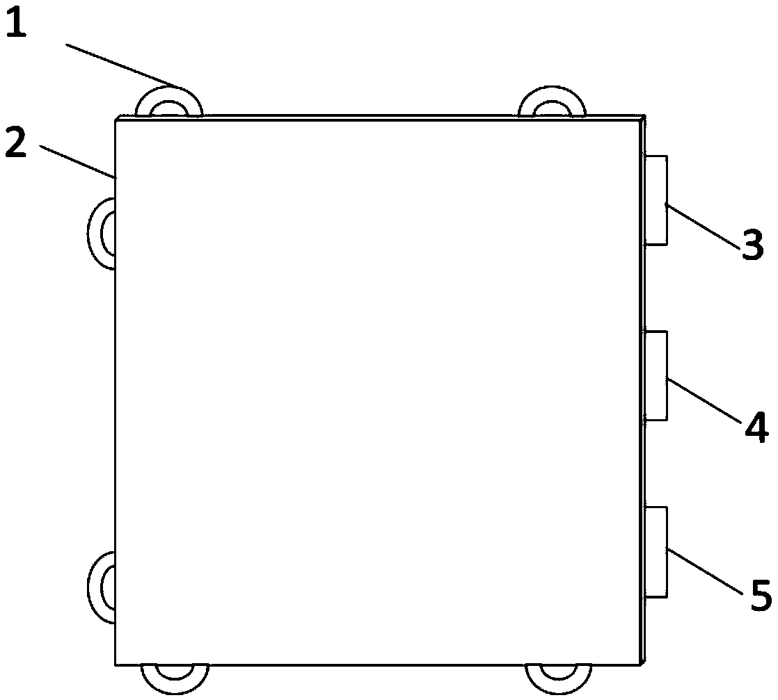
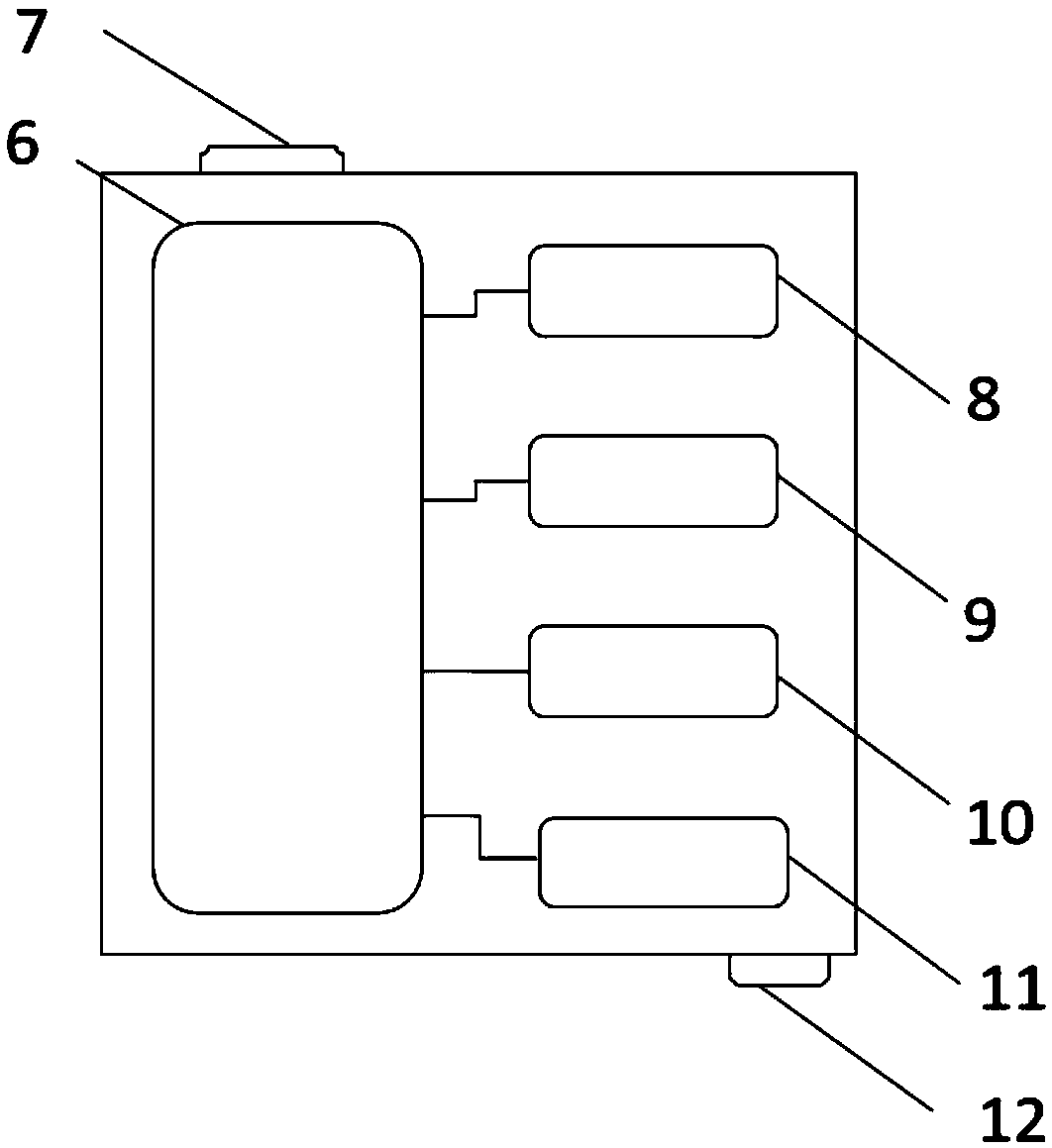
[0079] Such as figure 1 and figure 2 As shown, the DC servo drive system provided by the embodiment of the present invention includes: a fixed ferrule 1, a box body 2, a pulse signal interface terminal 3, a direction input interface terminal 4, an alarm output interface terminal 5, a PLC programmable controller 6, a DC Servo motor input terminal 7, DSP digital signal processor 8, PWM waveform transmitter 9, photoelectric encoder 10, rotary transformer 11, DC servo motor output terminal 12.
[0080] The fixed ferrule 1 is welded on the upper side, the lower side, and the outer edge of the left side of the box body 2, and the pulse...
PUM
 Abstract
Description
Claims
Application Information
 - R&D
- Intellectual Property
- Life Sciences
- Materials
- Tech Scout
- Unparalleled Data Quality
- Higher Quality Content
- 60% Fewer Hallucinations
Browse by: Latest US Patents, China's latest patents, Technical Efficacy Thesaurus, Application Domain, Technology Topic, Popular Technical Reports.
© 2025 PatSnap. All rights reserved.Legal|Privacy policy|Modern Slavery Act Transparency Statement|Sitemap|About US| Contact US: help@patsnap.com


