Semiautomatic continuous assembly machine for electromagnetic clutches

An electromagnetic clutch and semi-automated technology, applied in hand-held tools, manufacturing tools, etc., can solve the problems of low work efficiency, low degree of automation, high error rate, etc., and achieve the effect of improving work efficiency and saving labor costs

Active Publication Date: 2018-12-11
ZHEJIANG HANGTAI AUTO PARTS
View PDF8 Cites 1 Cited by
  • Summary
  • Abstract
  • Description
  • Claims
  • Application Information

AI Technical Summary

Problems solved by technology

[0005] The present invention aims at the deficiencies of the prior art and provides a semi-automatic continuous assembly machine for electromagnetic clutches. By setting a round cap laying mechanism on the transmission track of the triangular chassis, the round cap blanking assembly is placed on the transmission track of the triangular chassis. When the triangular chassis is feeding the round cap, it drives the triangular chassis pushing component to push the triangular chassis forward synchronously. At the same time, it cooperates with the elastic track linked with the round cap unloading component to realize the pressing process of the elastic track so that the triangular chassis is limited. On the platform, and the compression assembly is carried out by the compression component, replacing the original way of manually placing the workpiece, realizing the automatic production of blanking, pushing and limiting during the assembly process, and solving the low work efficiency in the prior art , low degree of automation, high error rate technical problems

Method used


Image

  • Semiautomatic continuous assembly machine for electromagnetic clutches
  • Semiautomatic continuous assembly machine for electromagnetic clutches
  • Semiautomatic continuous assembly machine for electromagnetic clutches

Examples


Embodiment 1

[0054] Embodiments of the present invention are described in detail below, examples of which are shown in the drawings, wherein the same or similar reference numerals designate the same or similar elements or elements having the same or similar functions throughout. The embodiments described below by referring to the figures are exemplary and are intended to explain the present invention and should not be construed as limiting the present invention.

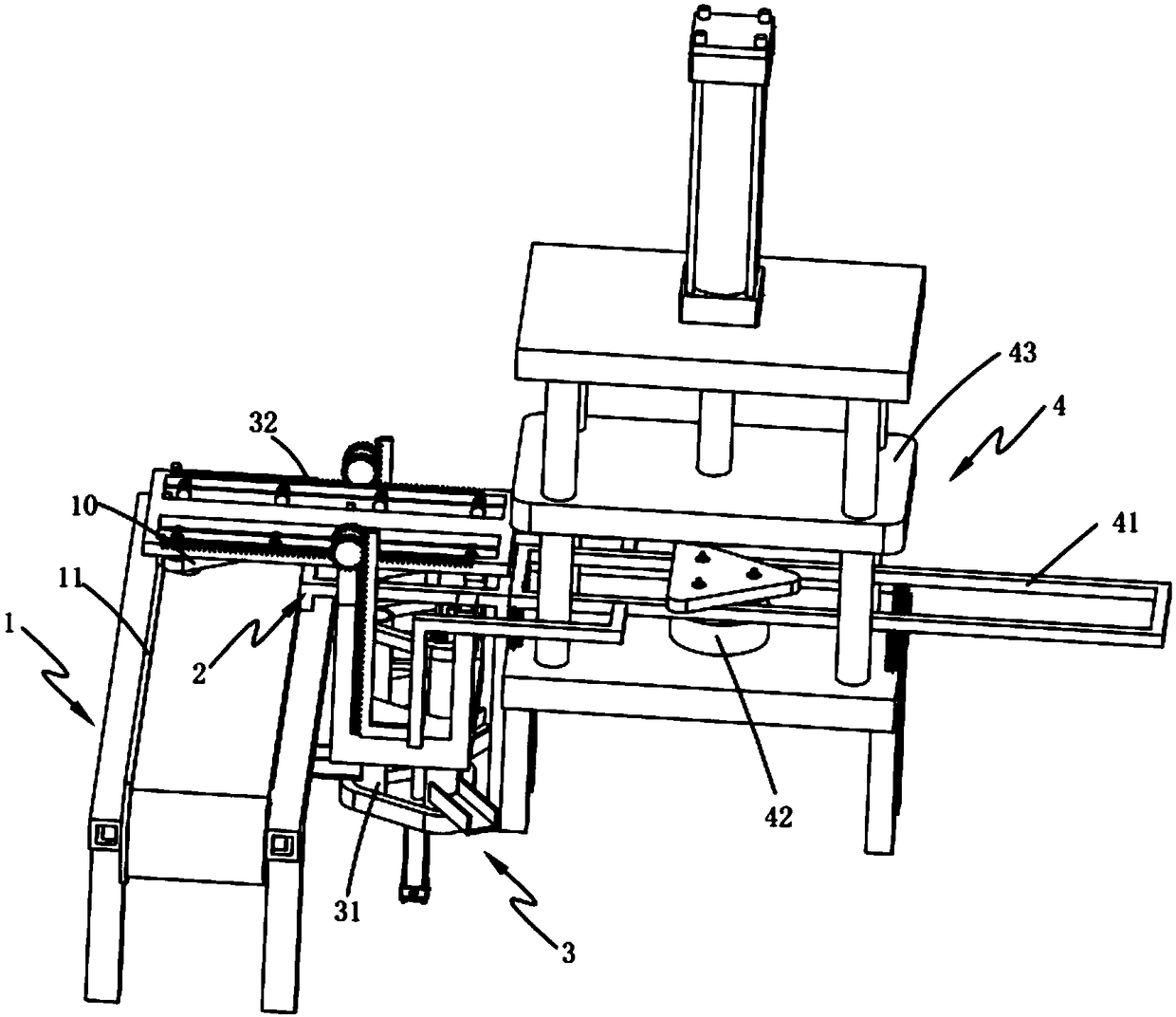
[0055] Such as Figure 1-15 As shown, an electromagnetic clutch semi-automatic continuous assembly machine includes a triangular chassis conveying mechanism 1 and a triangular chassis conveying track 2 arranged on one side of the triangular chassis conveying mechanism 1, and also includes:

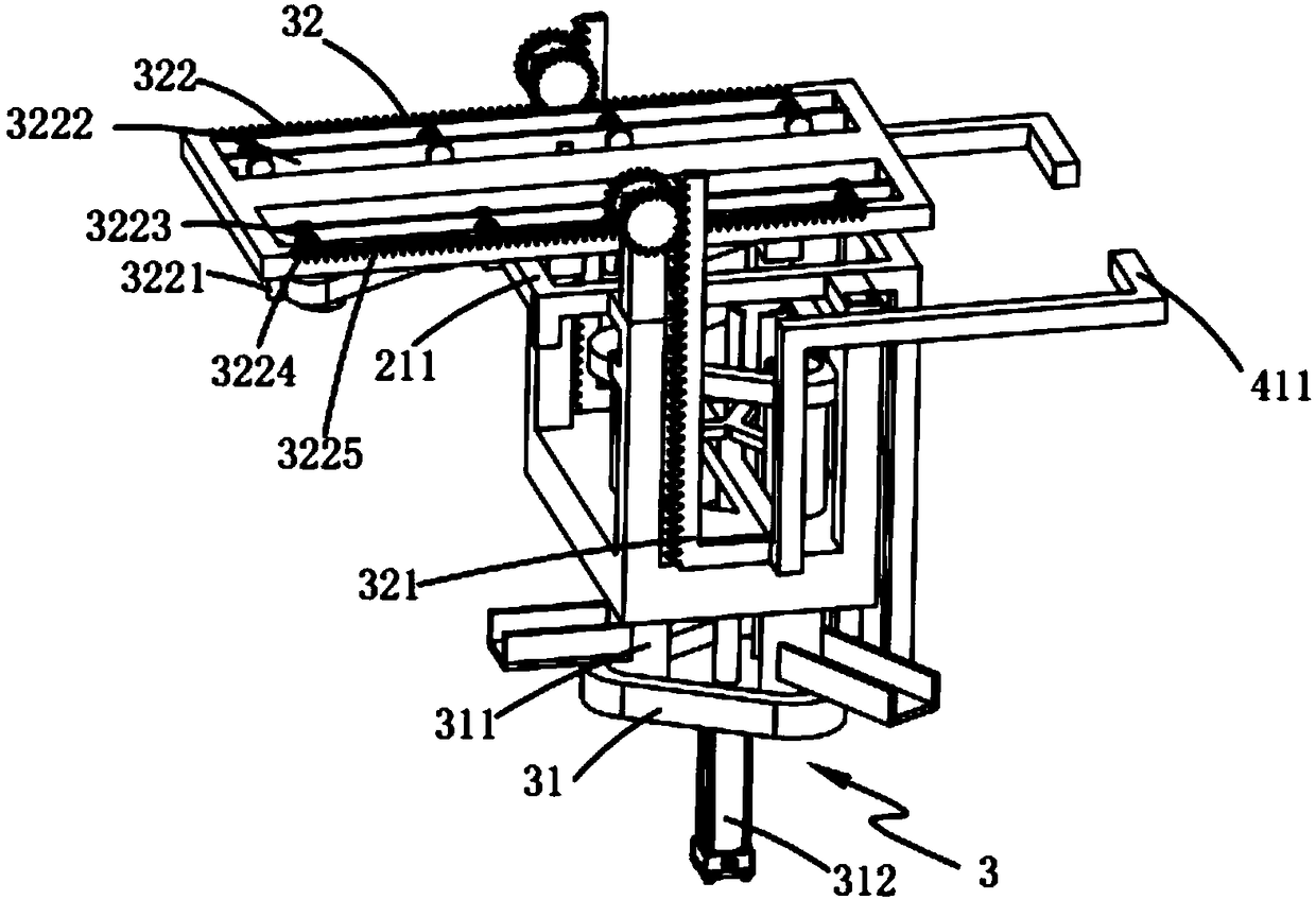
[0056] Round cap laying mechanism 3, described round cap laying mechanism 3 is arranged on the described triangular chassis transmission track 2, and this round cap laying mechanism 3 comprises round cap blanking assembly 31, triangular chass...

Embodiment 2

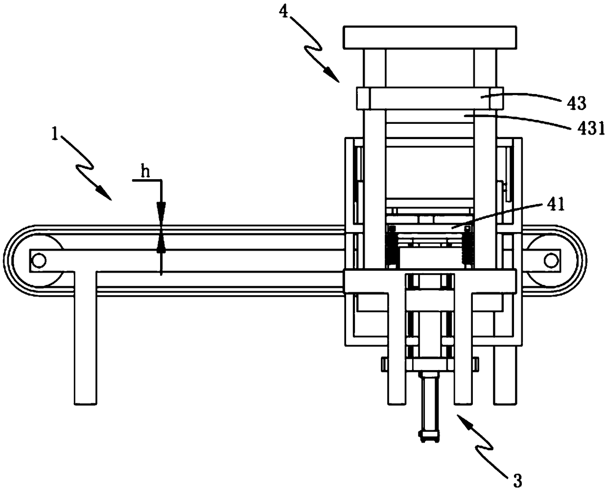
[0084] figure 2 It is a structural schematic diagram of Embodiment 2 of an electromagnetic clutch semi-automatic continuous assembly machine of the present invention; as figure 2 As shown, the parts that are the same as or corresponding to those in Embodiment 1 use the reference numerals corresponding to Embodiment 1. For the sake of simplicity, only the differences from Embodiment 1 will be described below. The difference between this embodiment two and the embodiment one shown in the figure is:

[0085] The transmission belt of the triangular chassis conveying mechanism 1 is provided with a limit projection 11 on one side away from the round cap laying mechanism 3, and the relationship between the height h of the limit projection 11 and the thickness H of the triangular chassis 10 satisfies , h

[0086] It should be noted that, by setting the limit protrusion 11 on the side of the transmission belt on the triangular chassis conveying mechanism 1 away from the round ca...


PUM


Abstract

The invention provides a semiautomatic continuous assembly machine for electromagnetic clutches, comprising a triangular baseplate conveying mechanism, a triangular baseplate conveying rail, a cap laying mechanism and an assembly compressing mechanism. The cap laying mechanism includes a cap feeding component and a triangular baseplate pushing component; the cap feeding component includes three groups of conveying barrels; the assembly compressing mechanism includes an elastic rail, a limiting platform and a compressing component; when the cap feeding component conveys a cap to a triangular baseplate, the cap laying mechanism arranged herein drives the triangular baseplate pushing mechanism to synchronously push the triangular baseplate forward, and under the cooperation of the elastic rail linked to the cap feeding component, the triangular baseplate is limited on the limiting platform when the elastic rail presses down and is compressed and fitted via the compressing component; feeding, pushing and limiting automation is achieved for the assembly process; the technical problems of the prior art, such as low working efficiency, low automation level and high error rate are solved.

Description

technical field [0001] The invention relates to the technical field of machinery for processing auto parts, in particular to an electromagnetic clutch semi-automatic continuous assembly machine. Background technique [0002] The automobile air conditioner clutch coil housing is stamped from a circular raw material steel plate. The equipment used is stamping forming equipment, which includes a punching machine, a feeding mechanism and a feeding mechanism; when in use, the feeding mechanism The raw steel plate in the feeding mechanism is transported to the punching station in the punch press, and the punch press punches the raw steel plate into a coil housing. However, the disadvantages of existing stamping and forming equipment are: the feeding mechanism in the equipment is generally a tray, and the manipulator used to take out the raw steel plate from the tray, when all the raw steel sheets in the tray are supplied After finishing, the equipment must be shut down and the tr...

Claims


Application Information

Patent Timeline
Patent Type & Authority Applications(China)
IPC IPC(8): B25B27/02
CPCB25B27/02
Inventor 沈生贤
Owner ZHEJIANG HANGTAI AUTO PARTS
Why Eureka
Try Eureka