
A semi-active control method and system for vortex vibration of a stiffened beam of a suspension bridge with a floating system

A semi-active control and suspension bridge technology, applied in the direction of suspension bridges, bridges, bridge construction, etc., can solve problems such as difficulties in making springs, social panic, and difficulty in adding aerodynamic measures, so as to reduce implementation difficulty, improve vortex vibration performance, and improve economy sexual effect

Active Publication Date: 2019-10-29
湖南省潇振工程科技有限公司
View PDF7 Cites 2 Cited by
  • Summary
  • Abstract
  • Description
  • Claims
  • Application Information

AI Technical Summary

Problems solved by technology

Secondly, the static elongation of the TMD spring is only determined by the natural frequency of the TMD. Assuming the vertical frequency f of the main beam is f=0.2Hz, the static elongation of the spring is about Δ=9.86 / (2πf) 2 = 6.25m, not only is it difficult to make the spring, but also it cannot be placed in the stiffened beam (the height of the stiffened beam generally does not exceed 5m)
On the other hand, it is also difficult to add aerodynamic measures to existing bridges
Because aerodynamic measures must be arranged along the entire span or most of the span of the bridge, the construction process of aerodynamic measures will inevitably affect the normal operation of the bridge, and may also cause certain social panic

Method used


Image

  • A semi-active control method and system for vortex vibration of a stiffened beam of a suspension bridge with a floating system
  • A semi-active control method and system for vortex vibration of a stiffened beam of a suspension bridge with a floating system
  • A semi-active control method and system for vortex vibration of a stiffened beam of a suspension bridge with a floating system

Examples


Embodiment Construction

[0040] Embodiments of the present invention will be described in further detail below in conjunction with the accompanying drawings.

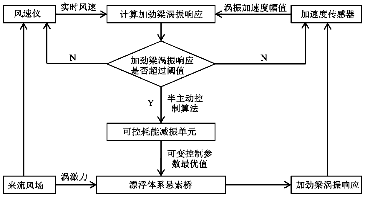
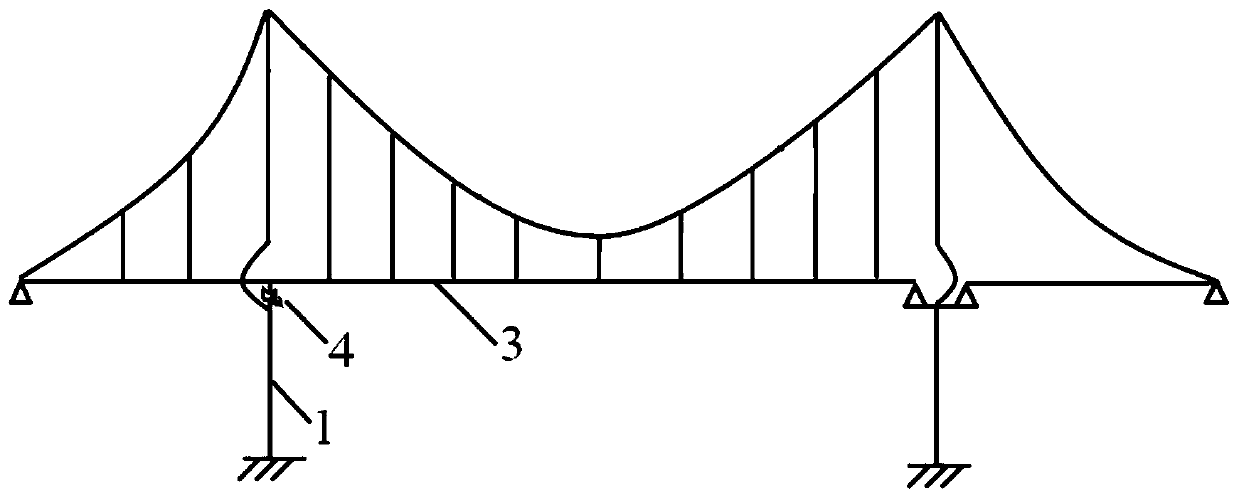
[0041] Such as figure 1 As shown, in this embodiment, the semi-active control method of the vortex vibration of the suspension bridge stiffening beam 3 in the floating system includes the following steps:

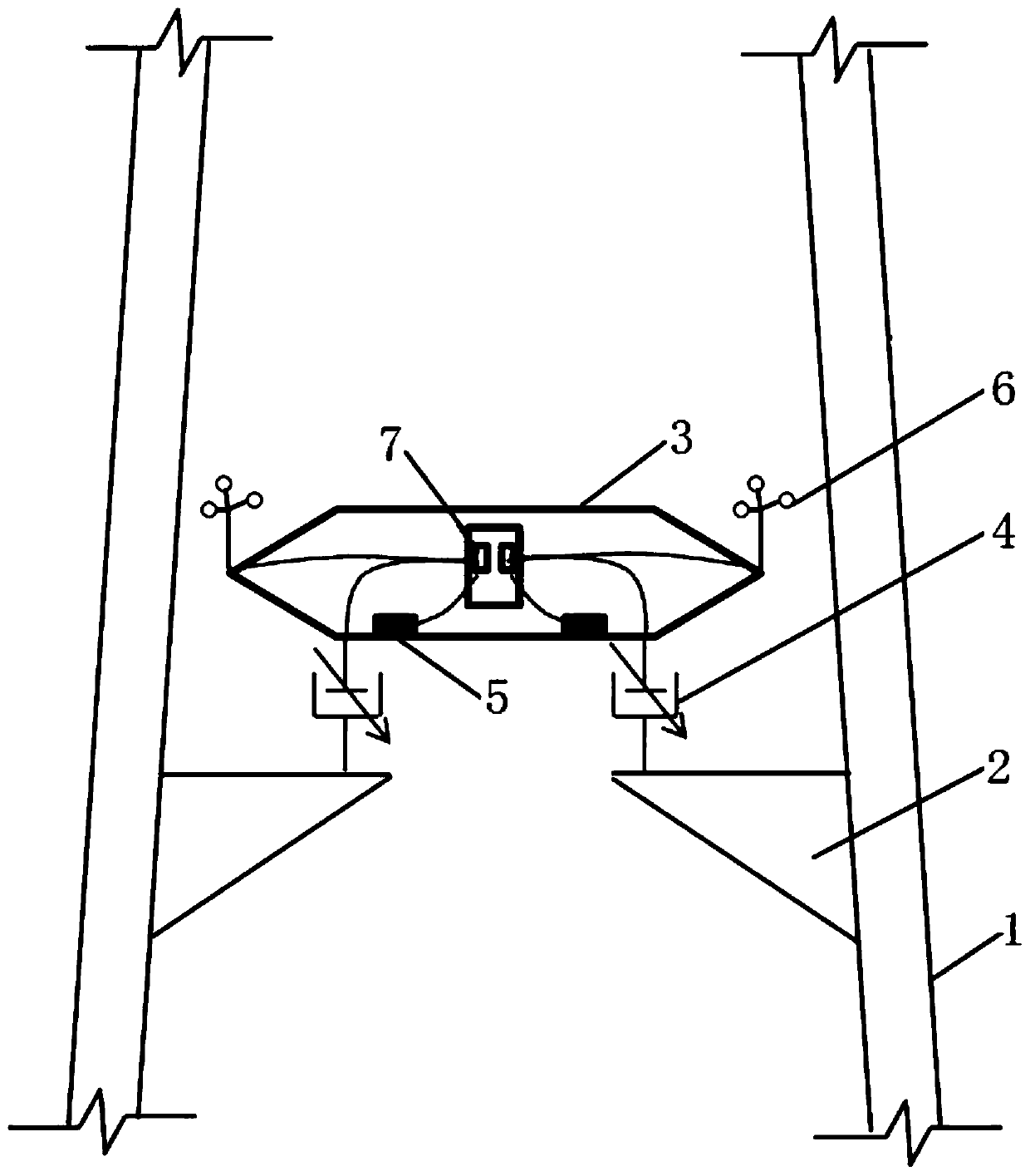
[0042] Step A. Between the corbel 2 on the lower tower column 1 and the floating stiffening beam 3, a controllable energy consumption vibration reduction unit 4 with vertical force output is arranged. The controllable energy dissipation vibration reduction unit 4 dissipates the vibration energy of the stiffening beam 3 by using the relative vertical motion between the stiffening beam 3 and the bridge tower during vortex vibration, thereby reducing the amplitude of the vortex vibration of the stiffening beam 3 . In this embodiment, the controllable energy dissipation vibration reduction unit 4 is a magneto-rheological damper.

[0043] Step ...


PUM


Abstract

The invention discloses a semi-active control method and a system for vortex vibration of a stiffening beam of a floating suspension bridge, wherein, the control method comprises the following steps:a controllable energy dissipation and vibration reduction unit is arranged between a bracket and a floating stiffening beam; collecting vibration response signals of stiffening girder and wind speed signals of bridge deck; judging whether the stiffening girder has vortex vibration response; if the vortex vibration response occurs, the corresponding structural modes are identified, and the amplitude of the vortex vibration response is judged to be greater than a set threshold value. if it is larger than, the variable control parameters of the controllable energy dissipation damping unit are calculated and adjusted to the optimal value by the semi-active control algorithm. The invention does not affect the normal operation of the bridge, simple ub structure, is easy to implement, can effectively control multi-mode vortex vibration of long-span floating suspension bridges, greatly reduce the difficulty of vibration control measures, improve the economy, reliability and robustness of vibration control measures, and ensure high vibration reduction efficiency even when structural parameters and inflow conditions are uncertain.

Description

technical field [0001] The invention belongs to the field of structural vibration control, in particular to a semi-active control method and system for vortex vibration of a stiffened beam of a suspension bridge in a floating system. Background technique [0002] Wind-induced stability is the controlling factor in the construction of super-long-span suspension bridges. The flutter stability of long-span suspension bridges can be significantly improved through aerodynamic selection and aerodynamic optimization, so that it can meet the construction needs of super-long-span suspension bridges with a main span of less than 2000m. However, the vortex vibration problem (especially the vertical vortex vibration problem) of stiffened beams of long-span suspension bridges has not been well solved. For example, my country's Xihoumen Bridge and Denmark's Dadaidong Bridge have observed vertical eddy vibrations with an amplitude of more than 20cm after the completion of the bridge under...

Claims


Application Information

Patent Timeline
Patent Type & Authority Patents(China)
IPC IPC(8): E01D19/00E01D11/02
CPCE01D11/02E01D19/00
Inventor 华旭刚陈政清黄智文徐凯牛华伟
Owner 湖南省潇振工程科技有限公司
Learn More