A method for erecting a cable-stayed suspension cable cooperative system bridge

A cable-stayed and suspended cable technology, applied in cable-stayed bridges, bridge construction, bridges, etc., can solve the problems of long side span cantilever, too large cable force difference of the main tower, prolonged construction period of beam erection, etc., saving construction period, Reduce the difficulty and improve the effect of stress

Inactive Publication Date: 2018-12-11
CHINA MAJOR BRIDGE ENERGINEERING
View PDF6 Cites 9 Cited by
  • Summary
  • Abstract
  • Description
  • Claims
  • Application Information

AI Technical Summary

Problems solved by technology

[0004] For railway bridges or cable-stayed and suspension-coordinated system bridges for both road and rail: On the one hand, the second-phase dead load of railway bridges or road-rail bridges accounts for a high proportion of the total dead load of the whole bridge. Before the main girder is closed, The second-stage dead load of the structure has not been applied yet. If the closing mouth is set in the overlapping section of the cable-stayed suspension cables, before the closing section is hoisted, the beam section of the suspension section will be several meters higher than the beam section of the cable-stayed section. If the above Erection method, at this time it will be extremely difficult to adjust the two ends of the closing mouth to meet the closing conditions; on the other hand, the side span is supported by a few auxiliary piers, because the stay cables in the overlapping section are stretched after the mid-span closing, overlapping The side-span beam sections corresponding to the section stay cables can only be constructed step by step after the mid-span is closed, following the tensioning of the stay cables in the overlapped section, resulting in extended beam erection period, long side-span cantilever time, and safety risks during construction. If the side-span beam section corresponding to the cable-stayed cable in the overlapping section is first installed and the corresponding cable-stayed cable is stretched, the cable force difference on both sides of the main tower will be too large, which is very unfavorable to the force of the main tower

Method used


Image

  • A method for erecting a cable-stayed suspension cable cooperative system bridge
  • A method for erecting a cable-stayed suspension cable cooperative system bridge
  • A method for erecting a cable-stayed suspension cable cooperative system bridge

Examples


Embodiment 1

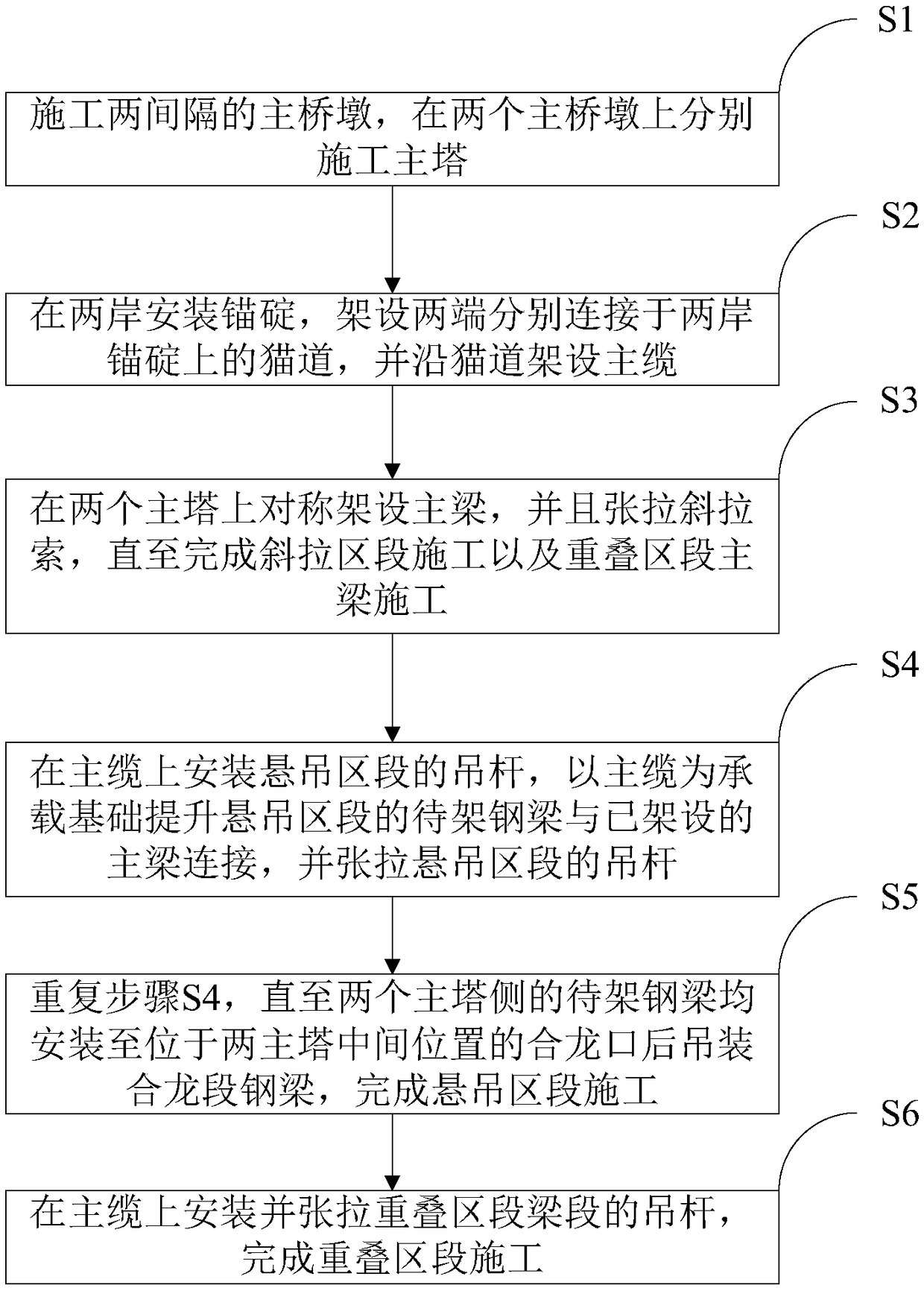
[0037] see figure 1 As shown, the embodiment of the present invention provides a bridge erection method of a cable-stayed and suspended cable cooperative system, comprising the following steps:

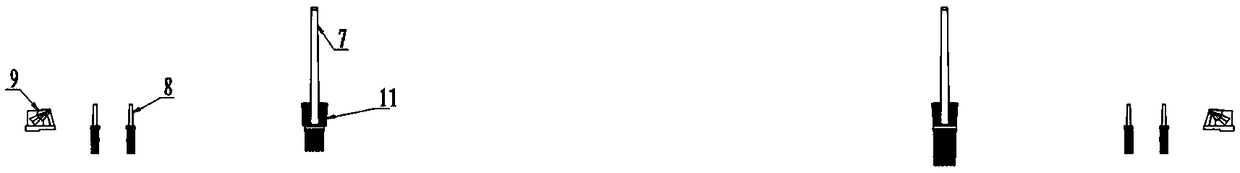
[0038] Step S1, see image 3 As shown, two main piers at intervals are constructed, and the main tower 7 is constructed respectively on the two main piers. Meanwhile, the side pier 8 between the main pier and the two sides can also be constructed, so as to improve the construction efficiency.

[0039] Step S2, see image 3 , Figure 4 As shown, the anchorage 9 is installed on both banks, and the catwalk 13 with two ends connected to the anchorage 9 on both sides of the bank is erected, and the main cable 1 is erected along the catwalk 13 .

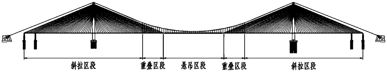
[0040] Step S3, see Figure 4 , Figure 5 As shown, the main girder 4 is erected symmetrically on the two main towers 7, and the stay cables 2 are stretched until the construction of the cable-stayed section and the construction of the main b...

Embodiment 2

[0045] On the basis of Embodiment 1, preferably, the main cable 1 and the main beam 4 of the cable-stayed section are erected synchronously, which can save construction time and cost. The main beam 4 of the cable-stayed section is gradually erected from the main tower 7 to both sides, The main girder 4 can be put on the pier as soon as possible to ensure the symmetry in the erection process of the main girder 4 and reduce the safety risk in the construction process.

Embodiment 3

[0047] On the basis of Example 1, the suspender 3 in the overlapping section is not stretched first, and after the construction of the overlapping section, the suspender 3 in the overlapping section is stretched, and the cable force of the whole bridge is adjusted to make the structure linear , internal forces, etc. reach the designed bridge state. Adopting this construction method ensures the symmetry in the erection process of the main beam 4, reduces the bending moment of the main tower 7, improves the stress of the main tower in the erection process, and ensures construction safety.


PUM


Abstract

The invention discloses a method for erecting a cable-stayed suspension cable cooperative system bridge, which relates to the technical field of bridge construction. The method comprises the followingsteps of: constructing two spaced main piers and main towers; installing anchorages, erecting catwalks and erectingmain cables along catwalks; erecting the main girder and tensioning the stay cablesto complete the construction of the stay section and the main girder of the overlapping section; arranging suspension rod - on that main cable, wherein the steel beam to be erected is connected with the erected main beam, and the suspension rod of the suspension section is tensioned; reapting the above steps until the steel beams to be erected are installed at the closure opening between the two main towers, and then hoisting the steel beams of the closure section to complete the construction of the suspension section; installing and tensioning the boom of the overlapping section beam sectionto complete the construction of the overlapping section. A main beam close mouth of that invention is one, and the symmetry of the bridge structure is utilized to ensure that the height difference ofthe main beam on both sides of the main beam close mouth is small, thereby reducing the difficulty of closing the main beam, improving the safety risk in the main beam erection process, and improvingthe construction efficiency.

Description

technical field [0001] The invention relates to the technical field of bridge construction, in particular to a bridge erection method of a cable-stayed and suspended cable cooperative system. Background technique [0002] The cable-stayed-suspension cooperative system bridge has the advantages of high rigidity of the cable-stayed bridge and strong spanning ability of the suspension bridge. The axial pressure of the main girder is smaller than that of the same-span cable-stayed bridge, and the main tower is lower than that of the same-span cable-stayed bridge; the stiffness is larger than that of the same-span suspension bridge, and the size of the main cable and anchorage is smaller than that of the same-span suspension bridge. Therefore, it can be used as an optimal solution for super-long-span railway bridges that require higher structural rigidity. [0003] Chinese Invention Patent Specification CN201510719351.2 discloses an overall construction method for a partial grou...

Claims


Application Information

Patent Timeline
Patent Type & Authority Applications(China)
IPC IPC(8): E01D21/10E01D11/04
CPCE01D11/04E01D21/10
Inventor 肖海珠何东升潘韬高宗余张晓勇刘俊锋
Owner CHINA MAJOR BRIDGE ENERGINEERING
Why Eureka
Try Eureka