Concrete member plug connector and connection structure

A plug-in joint, concrete technology, applied in the direction of building structure, construction, etc., can solve problems such as plug-in failure, achieve the effect of convenient plug-in, large friction, and prevent poor or failure of plug-in

Inactive Publication Date: 2018-12-11
天海钢棒(张家港)有限公司
View PDF0 Cites 4 Cited by
  • Summary
  • Abstract
  • Description
  • Claims
  • Application Information

AI Technical Summary

Problems solved by technology

[0003] In view of the above problems, the present invention researches and designs a concrete component plug joint, which has a simple structure and can solve the disadvantages of existing plugs that are prone to plug failure.

Method used


Image

  • Concrete member plug connector and connection structure
  • Concrete member plug connector and connection structure
  • Concrete member plug connector and connection structure

Examples


Embodiment 1

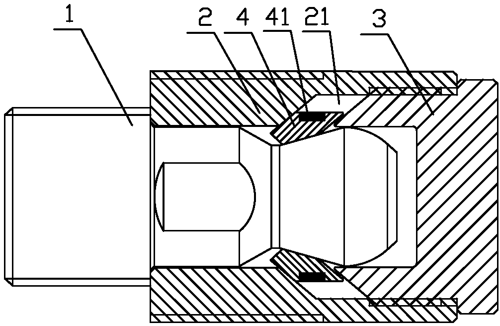
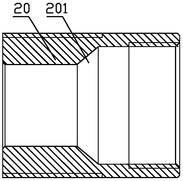
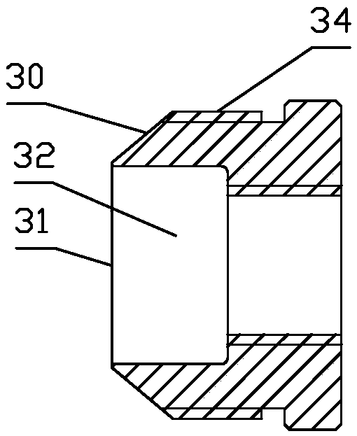
[0030] Such as figure 1 As shown, a plug joint for concrete components includes a plug 1 , a connecting sleeve 2 , a guide 3 and a split snap ring 4 . Such as figure 2 As shown, the inner side of one end of the connecting sleeve 2 is provided with a radially inwardly protruding card platform 20, and the other end is fixed with the guide 3. In this embodiment, the guide 3 is fixed on the connection by a thread 34. In the sleeve 2, the clamping table 20 is provided with a frusto-conical clamping surface 201 at one end facing the guide member 3, such as Figure 3a and Figure 3b As shown, the end of the guide member 3 facing the card table 20 is a guide end 31, and the guide end 31 is provided with a frustum-conical guide surface 30, so that the guide end 31 is in a frustum-shaped structure. The surface 201 and the guide surface 30 are opposite to form a guide groove 21 for accommodating the split snap ring. The guide end 31 is provided with a correction cavity 32 capable of ...

Embodiment 2

[0038] Such as Figure 7 and Figure 8 As shown, a concrete component connection structure includes the concrete component plug joint disclosed in the present invention, and also includes a first end plate 50 and a second end plate 51, and the plug 1 is fixed on the first end plate 50, the connecting sleeve 2 is fixed on the second end plate 51, and the first end plate 50 and the second end plate 51 are fixed to each other by bonding or welding, specifically by sticking steel glue or The edges are fully welded for fixation.

[0039] In this embodiment, the first end plate 50 and the second end plate 51 have the same structure, such as Figure 9 As shown, the first end plate is provided with a first fixing hole 500, and the second end plate is provided with a second fixing hole 510. In this embodiment, since the first end plate and the second The end plates have the same structure, so the labels of the first fixing hole and the second fixing hole are marked in the same figur...


PUM


Abstract

The invention discloses a concrete member plug connector comprising a connector, a connecting sleeve, a guide element and a split snap ring. The concrete member plug connector is characterized in thatthe inner side of one end of the connecting sleeve is provided with a radially inwardly protruding card table, while the other end of the connecting sleeve is fixed with the guide element; one end, facing the guide element, of the card table is provided with a circular cone-shaped clamping surface; one end, facing the card table, of the guide element is a guide end which is provided with a circular cone-shaped guide surface; the clamping surface and the guide surface relative to each other form a guide groove for accommodating the split snap ring; the guide end is provided with a correction cavity capable of correcting the insertion direction of the connector; the split snap ring includes more than three circumferentially stitched latches; the outer side of each latch is sleeved with an elastic ring with radial elasticity; the connector can pass through the split snap ring to expand the split snap ring in the guide groove, and the connector is snapped and fixed by the rebound of the elastic ring. The concrete member plug connector has various advantages such as a simple structure, and easy and highly-efficient plug connection.

Description

technical field [0001] The invention relates to a prefabricated concrete component connection structure, in particular to a concrete component plug joint and a connection structure. Background technique [0002] In recent years, precast concrete components have been widely used in the construction industry. When using precast concrete components, it is often necessary to connect multiple components. Therefore, connection structures such as mechanical plug joints have also been derived. Mechanical joints are easy to plug in and excellent. The anti-pulling and anti-corrosion properties of the industry have been favored by more and more producers and users in the industry, but the existing joints have the following problems. The applicant cut and inspected the mechanical connection parts of the prefabricated components and found that the existing plug joints During the insertion process of the plunger, there is a situation where the connector fails to connect. Since the connect...

Claims


Application Information

Patent Timeline
Patent Type & Authority Applications(China)
IPC IPC(8): E04B1/41
CPCE04B1/4157E04B1/4114
Inventor 袁雪峰
Owner 天海钢棒(张家港)有限公司
Why Eureka
Try Eureka