a combination co 2 Captured heat grid water staged heating system

A technology of grading heating and heating network water, applied in heating systems, hot water central heating systems, heating methods, etc., can solve the problems of reduced difficulty in utilization of waste heat, large limitations, and less heating temperature range.

Active Publication Date: 2020-07-07
SOUTHEAST UNIV
View PDF6 Cites 0 Cited by
  • Summary
  • Abstract
  • Description
  • Claims
  • Application Information

AI Technical Summary

Problems solved by technology

[0009] On the other hand, currently the CO 2 Combined capture and heat supply methods are rare and can only meet specific heat supply temperature ranges
For example, CN102322301A discloses a CO 2 Capture-heating integrated system and method, aimed at capturing CO by chemical absorption 2 A single unit that will capture CO 2 The low-temperature heat generated in the process is used for floor heating, and the heating temperature is 35-60°C, which has great limitations
CN106215682A discloses a combination of calcium cycle capture CO 2 The method of combined heat, power and cooling triple generation system realizes the zero carbon emission of the triple generation system, and can simultaneously realize heating, cooling, power generation and CO 2 capture, but this method is aimed at the calcium cycle carbon capture technology, and the carbon capture temperature is relatively high (above 600°C), so the difficulty of waste heat utilization is greatly reduced, and it is essentially different from the system and method proposed by the present invention

Method used


Image

  • a combination co  <sub>2</sub> Captured heat grid water staged heating system
  • a combination co  <sub>2</sub> Captured heat grid water staged heating system
  • a combination co  <sub>2</sub> Captured heat grid water staged heating system

Examples


Embodiment Construction

[0027] The present invention will be further explained below in conjunction with the accompanying drawings and specific embodiments. It should be understood that the following specific embodiments are only used to illustrate the present invention but not to limit the scope of the present invention.

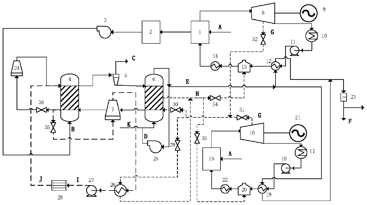
[0028] figure 1 It is a structural schematic diagram of the present invention, and the list of reference signs: 1 is the first boiler, 2 is the flue gas treatment device, 3 is the booster fan, 4 is the carbonation reactor, 5 is the cyclone separator, 6 is the regeneration reactor, 7 is the adsorbent cooling tower, 8 is the first steam turbine, 9 is the first generator, 10 is the first condenser, 11 is the first condensate pump, 12 is the first heat exchanger, 13 is the first deaerator , 14 is the first high pressure heater, 15 is the second boiler, 16 is the second steam turbine, 17 is the second condenser, 18 is the second condensate pump, 19 is the second heat exchanger, 20 is ...


PUM


Abstract

The invention discloses a heating network water grading heating system combined with CO2 capture. The heating network water grading heating system comprises a generating system of a first extraction condensing unit, a generating system of a second extraction condensing unit, a carbon capture subsystem and a heating network water system. Extraction steam of two turbines is mixed and then distributed again, part of the extraction steam is used for heating a regenerative reactor in a carbon capture system, and the other part of the extraction steam is used for heating a peak-load calorifier. Hydrophobic water subjected to heat emission is mixed and then distributed again, and returns to corresponding deaerators. The low-temperature heating network return water is primarily heated through heatemission of a carbonation reactor in the carbon capture process, then intermediately heated through the cooling process of a high-temperature adsorbent in an adsorbent cooling tower, and finally, heated by the peak-load calorifier. Grading heating of the heating network water is achieved through large-scale heat emission of different grades in the CO2 capture process through a low-temperature drymethod, emission of CO2 is reduced while energy gradient utilization is achieved, and the whole system has good innovativeness and practicalness.

Description

technical field [0001] The present invention relates to a combination of CO 2 The utility model relates to a grading heating system of captured heat network water, which belongs to the technical field of central heating and carbon dioxide emission reduction. Background technique [0002] Cogeneration of heat and power refers to a production method in which a power plant uses steam that has been done work to provide heat to users while generating electricity. Compared with conventional power plants, thermal power plants have greatly reduced the loss of cold sources, and their thermal efficiency is much higher than that of ordinary pure condensing power plants, thus greatly improving energy utilization efficiency and saving fuel. From the perspective of controlling environmental pollution, central heating is also conducive to reducing coal consumption and reducing pollutant emissions. Generally speaking, the more common heating method for thermal power plants is to use the s...

Claims


Application Information

Patent Timeline
Patent Type & Authority Patents(China)
IPC IPC(8): F24D3/10F01K11/02F01K17/02F01K25/10
CPCF01K11/02F01K17/02F01K25/103F24D3/10
Inventor 陈晓平谢玮祎梁财刘道银马吉亮
Owner SOUTHEAST UNIV
Why Eureka
Try Eureka