Composite water-cooled wall, water-cooled flue and water-cooled furnace lid

A composite, water-cooled wall technology, applied in furnaces, furnace cooling, furnace components, etc., can solve the problems of high thermal conductivity, low thermal conductivity, large heat loss, etc. The effect of equipment life

Pending Publication Date: 2018-12-11
CISDI ENG CO LTD
View PDF0 Cites 0 Cited by
  • Summary
  • Abstract
  • Description
  • Claims
  • Application Information

AI Technical Summary

Problems solved by technology

The light-tube water-cooled wall is made of continuous welding of seamless steel pipes, which has a simple structure and is easy to manufacture, but has a high thermal conductivity and large heat loss
Membrane water-cooled wall is made of water-cooled tubes (bare tubes or finned tubes) and flat steel interlaced welded. It has good sealing performance, but its rigidity is poor, and it is prone to thermal deformation or damage.
The pin-type water-cooled wall is made by welding a number of cylindrical pins on the outside of the light-pipe water-cooled wall and covering it with refractory materials. The thermal conductivity is low, but the refractory materials are concentrated in sheets, which is prone to cracking or even falling off of the refractory material due to uneven thermal stress.

Method used


Image

  • Composite water-cooled wall, water-cooled flue and water-cooled furnace lid
  • Composite water-cooled wall, water-cooled flue and water-cooled furnace lid
  • Composite water-cooled wall, water-cooled flue and water-cooled furnace lid

Examples


Embodiment 1

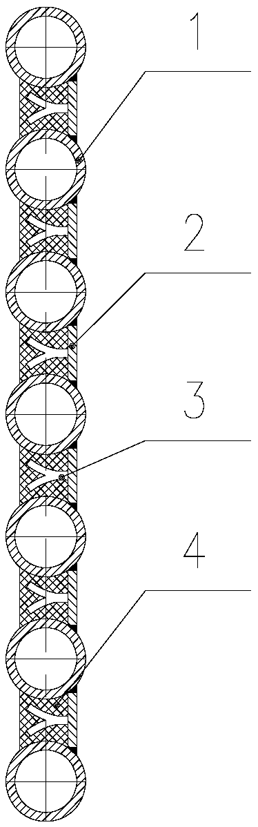
[0032] refer to figure 1 , 4 , the composite water-cooled wall of this embodiment is mainly composed of a water-cooled tube 1, a sealing plate 2, a slag-hanging nail 3, and a refractory material 4. The sealing plate 2 is arranged on the back side of the water-cooled tube 1 and is used for single-sided sealing and connection. The water-cooled pipe 1 of the circuitous structure, the circuitous structure adopts a serpentine spaced arrangement structure, of course, in different embodiments, a circuitous spaced structure can also be used, and the sealing plate adopts a block type, that is, the sealing plate includes multiple, and are respectively located in the detour interval area a of the water-cooling pipe, the sealing plate 2 is directly welded to the water-cooling pipe 1, and the sealing plate 2 is provided with several The slag-hanging nails 3 are arranged in a criss-cross arrangement on the sealing plate 2, and the two are connected by welding. The refractory material 4 is ...

Embodiment 2

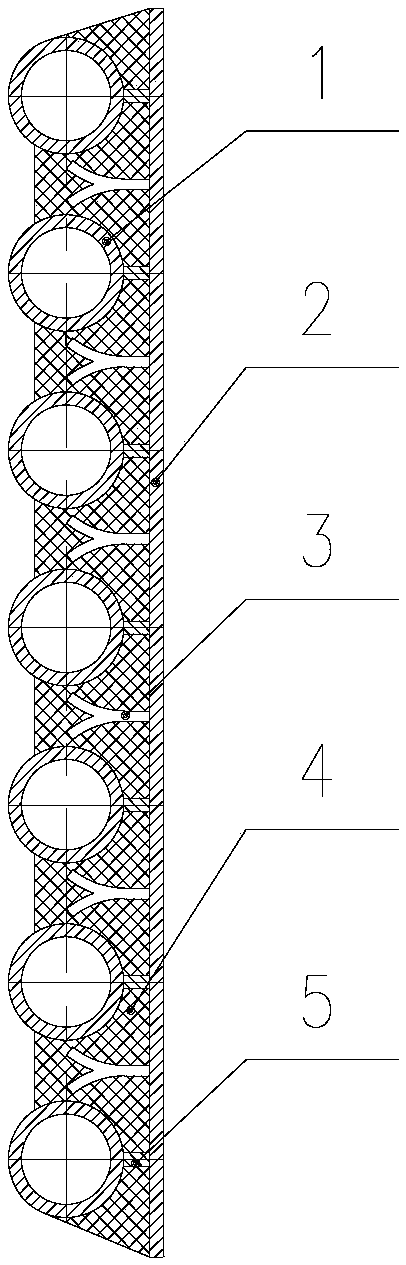
[0034] Such as figure 2 As shown, the difference between the present embodiment and the first embodiment is that the sealing plate adopts a monolithic structure, and the sealing plate and the water-cooling tube are welded through stiffener plates. In this way, the amount of refractory material used in the detour interval area a of the water-cooled pipe 1 can be increased, and the high-temperature resistance performance of the composite water-cooled wall can be further improved.

Embodiment 3

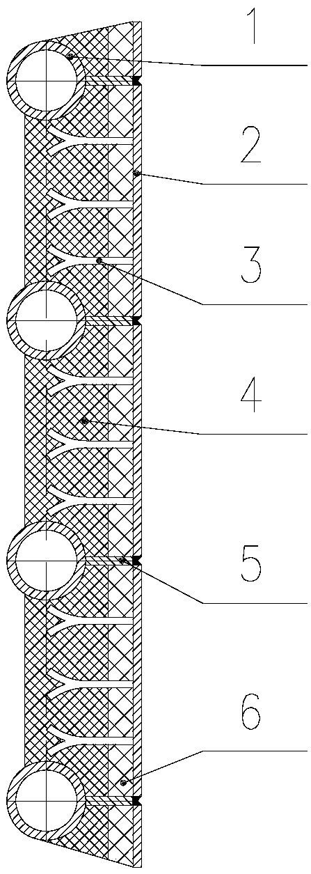
[0036] Such as image 3 As shown, the difference between this embodiment and the second embodiment is that a heat insulating layer 6 is added between the sealing plate 2 and the refractory material 4 . The high temperature resistance performance of the composite water wall can be further improved.

[0037] Additionally, if Figure 5 , 6 , 7, the present invention also provides a water-cooled flue, which is enclosed by the above-mentioned composite water-cooled wall, and its cross-sectional shape can be rectangular, circular or runway-shaped; or variable cross-section structures.

[0038] Additionally, if Figure 8 , 9 As shown, the present invention also provides a water-cooled furnace cover made of the above-mentioned composite water-cooled wall. It can be used for the furnace cover of electric arc furnace and LF furnace.


PUM


Abstract

The invention discloses a composite water-cooled wall suitable for long-term working in a high temperature environment, and belongs to the field of metallurgical equipment. The composite water-cooledwall comprises water cooling pipes, sealing plates, slag adhering nails and refractory materials. The sealing plates are arranged on the back heating sides of the water cooling pipes and used for being in single-sided sealed connection with the water cooling pipes of a periphrastic structure, and the multiple slag adhering nails are arranged at the positions, in the periphrastic interval area of the water cooling pipe, of the sealing plates and on the deviating faces, back away from the back heating sides of the water cooling pipes. The refractory materials are arranged on the heated sides ofthe water cooling pipes and used for filling the periphrastic interval area of the water cooling pipes, and the slag adhering nails are wrapped with the refractory materials. According to the composite water-cooled wall, the radiation heat loss can be effectively reduced, the use amount of cooling water is decreased, the soundness of the refractory materials is maintained, the service life of equipment is prolonged, and the composite water-cooled wall is of great significance for energy saving and consumption reduction.

Description

technical field [0001] The invention belongs to the technical field of metallurgical equipment, and in particular relates to a composite water-cooled wall suitable for working in a high-temperature environment for a long time, and is suitable for part or all of the water-cooled parts such as furnace covers and water-cooled flues of electric arc furnaces and LF furnaces. Background technique [0002] The water-cooled parts such as the furnace cover and water-cooled flue of the electric arc furnace and LF furnace not only need to work for a long time in abnormally harsh conditions such as high-temperature baking, strong magnetic radiation, and dust erosion, but also need to ensure that the equipment is water-cooled while reducing heat loss to achieve energy saving. Therefore, it is particularly important for the above-mentioned water-cooling parts to have high temperature resistance, low heat conduction and other properties. [0003] At present, the above-mentioned water-cooli...

Claims


Application Information

Patent Timeline
Patent Type & Authority Applications(China)
IPC IPC(8): F27D9/00
CPCF27D9/00F27D2009/0013
Inventor 施维枝黄其明谈存真高瞻
Owner CISDI ENG CO LTD
Why Eureka
Try Eureka