
Laser thickness measuring system and method

A technology of laser thickness measurement and laser beam, which is applied to measurement devices, optical devices, instruments, etc., can solve problems such as difficulty in precise synchronous movement, vibration of upper and lower beams of C-shaped frames, thickness measurement deviation of micron level, etc. The effect of precision and vibration resistance

Inactive Publication Date: 2018-12-11
SHENZHEN XINYUREN TECH
View PDF10 Cites 14 Cited by
  • Summary
  • Abstract
  • Description
  • Claims
  • Application Information

AI Technical Summary

Problems solved by technology

The laser thickness measuring device in the above-mentioned existing equipment is usually based on the thickness measurement form of the C-shaped frame scanning thickness measurement design. Although this C-shaped frame has been widely used, in the actual measurement process, due to the back and forth scanning process of the C-shaped frame There is a large mechanical vibration in the center, which will cause the vibration or even slight deformation of the upper and lower beams of the C-shaped frame, which will make the distance between the upper and lower laser heads unstable, and will cause a large deviation for micron-level thickness measurement
Disclosed in CN106152952A is a differential on-line laser thickness measurement system capable of multi-point correction. Although it solves the measurement deviation caused by the unstable distance between the upper and lower laser heads, its two laser displacement sensors are located on different tracks. It is difficult to achieve precise synchronous movement

Method used


Image

  • Laser thickness measuring system and method
  • Laser thickness measuring system and method
  • Laser thickness measuring system and method

Examples


Embodiment Construction

[0029] In order to make the object, technical solution and advantages of the present invention clearer, the present invention will be further described in detail below in conjunction with the accompanying drawings and embodiments. It should be understood that the specific embodiments described here are only used to explain the present invention, not to limit the present invention. In addition, the technical features involved in the various embodiments of the present invention described below can be combined with each other as long as they do not constitute a conflict with each other.

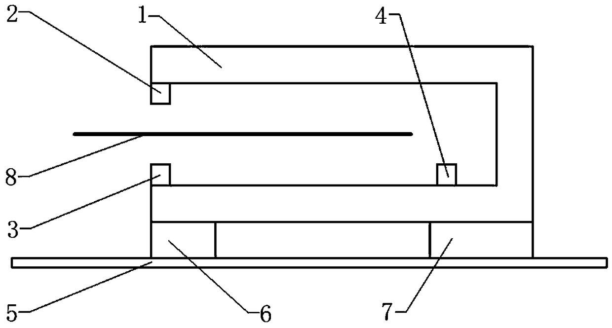
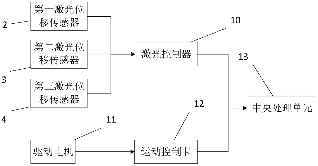
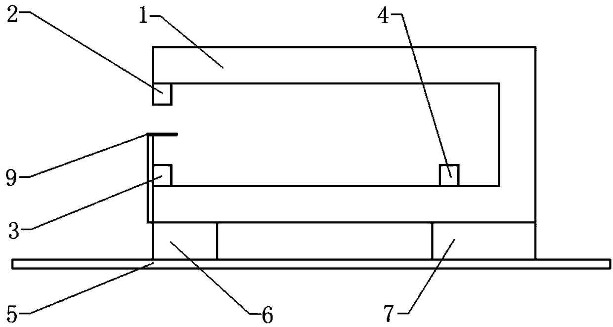
[0030] Such as figure 1As shown, a laser thickness measurement system provided by the embodiment of the present invention has a main body of the device as a C-shaped frame 1, and the C-shaped frame 1 is installed on a guide rail 5 arranged horizontally. The C-shaped frame 1 has an upper beam and a lower beam, and the area between the upper beam and the lower beam is used to place the film 8 to ...


PUM


Abstract

The invention relates to a laser thickness measuring system and method. Laser displacement sensors are mounted in the ends of upper and lower beams of a C-shaped rack respectively, and the inner sideof the lower beam of the C-shaped rack is further provided with a laser displacement sensor; before thickness measurement, a standard sheet measures the distance Y between the upper and lower displacement sensors and the distance X from the laser displacement sensor in the inner side of the lower beam to the upper beam by scanning, the one-to-one correspondence between Y and X is determined aftermeasurement for multiple times, and a function relation is fit; and in the practical film thickness measuring process, in any scanning position, the laser displacement sensor at the ends of the upperand lower beams of the C-shaped rack measure the distance A from the upper laser displacement sensor to the upper surface of a film and the distance B from the lower laser displacement sensor to the lower surface of the film respectively, and the laser displacement sensor in the inner side of the lower beam of the C-shaped rack measures the position X to the upper beam. The distance between the upper and lower laser displacement sensors is measured dynamically in each scanning position, and a measurement result is more accurate.

Description

technical field [0001] The invention belongs to the field of non-contact online thickness measurement of thin films, and more specifically relates to an online laser thickness measurement system and measurement method for thin films. Background technique [0002] In industrial production such as lithium battery pole piece coating and metal foil production line, the uniformity of the thickness of the strip determines the quality of the final product, so the online thickness detection of the strip is very important. For the thickness measurement of non-transparent films such as lithium battery coated pole pieces and metal foils, the more commonly used online thickness measurement method is the upper and lower differential laser triangulation method, that is, the upper and lower laser heads are used to measure the thickness of the upper and lower laser heads respectively. The distance to the upper and lower surfaces of the film is subtracted from the distance between the upper ...

Claims


Application Information

Patent Timeline
Patent Type & Authority Applications(China)
IPC IPC(8): G01B11/06G01B11/02
CPCG01B11/02G01B11/06
Inventor 杨志明周华民张云
Owner SHENZHEN XINYUREN TECH
Learn More