
Force measuring ring and crane

A force measuring ring and crane technology, which is applied in the measurement, transportation and packaging of the elastic deformation force of the measuring gauge, and the load hanging components, etc., can solve the problems of short life, changing shrapnel opening amount, and low accuracy, etc., to achieve The effect of compensating for measurement deviations

Pending Publication Date: 2022-04-29
苏州凯德斯电子科技有限公司
View PDF0 Cites 0 Cited by
  • Summary
  • Abstract
  • Description
  • Claims
  • Application Information

AI Technical Summary

Problems solved by technology

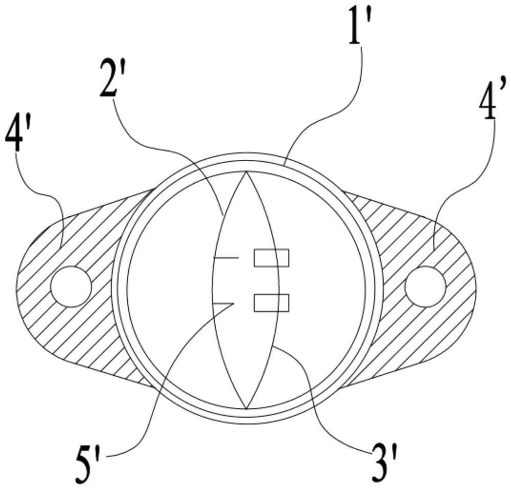
[0005] However, if figure 1 The force measuring ring shown has the following defects: (1) It can only output several switch signals, and cannot continuously output weight signals, which is not convenient for signal processing of the control system
(2) It is greatly affected by temperature. When the weight limiter "expands and contracts" at different temperatures, the opening amount of the shrapnel will change, and the accuracy is not high
(3) The use of contact measurement method has a short life, and the accuracy will be affected by the wear, rust and pollution of the contacts.
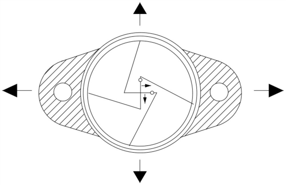
However, in this patent, the bending arcs of the first deformation piece and the second deformation piece are in the same direction, which leads to a slight change in the distance between the two deformation pieces when the force measuring ring is subjected to tension, which leads to the final The measurement error is large and the measurement result is inaccurate

Method used


Image

  • Force measuring ring and crane
  • Force measuring ring and crane
  • Force measuring ring and crane

Examples


Embodiment Construction

[0025] The following will clearly and completely describe the technical solutions in the embodiments of the present invention with reference to the accompanying drawings in the embodiments of the present invention. Obviously, the described embodiments are only some, not all, embodiments of the present invention. Based on the embodiments of the present invention, all other embodiments obtained by persons of ordinary skill in the art without making creative efforts belong to the protection scope of the present invention.

[0026] It should be noted that in the description of the present invention, terms such as "first" and "second" are only used to describe the purpose and distinguish similar objects, there is no sequence between the two, and they cannot be interpreted as indicating or imply relative importance. In addition, in the description of the present invention, unless otherwise specified, "plurality" means two or more.

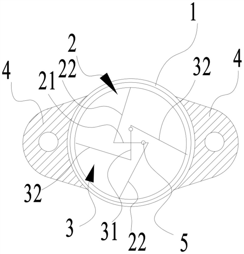
[0027] like Figures 2 to 4 As shown, it is a fo...


PUM


Abstract

The invention provides a dynamometric ring and a crane, the dynamometric ring comprises an annular shell, and the two ends of the shell are stress ends; the first elastic piece and the second elastic piece are arranged in the annular shell in a crossed mode, the first elastic piece and the second elastic piece are Z-shaped elastic pieces, the first elastic piece comprises a first rotating part and two first compression parts connected to the two ends of the first rotating part respectively, and the second elastic piece comprises a second rotating part and two second compression parts connected to the two ends of the second rotating part respectively. The first elastic piece comprises a first rotating part and two first compression parts connected to the two ends of the first rotating part respectively, the second elastic piece comprises a second rotating part and two second compression parts connected to the two ends of the second rotating part respectively, the first rotating part and the second rotating part are arranged in a crossed mode, the free ends of the two first compression parts are connected to the shell respectively, and the free ends of the two second compression parts are connected to the shell respectively. According to the proving ring and the crane, the deformation amount of the proving ring is obtained by continuously measuring the cross included angle of the two Z-shaped elastic sheets. And the magnitude of the force borne by the force measuring ring can be continuously output.

Description

technical field [0001] The invention relates to the field of hoisting equipment, in particular to a force measuring ring and a crane. Background technique [0002] The statements in this section only provide background information related to the present disclosure and may not constitute prior art. [0003] At this stage, the weight limit of tower cranes is mostly achieved by measuring the force-measuring ring change on the wire rope. That is: after the load is loaded, the force measuring ring is deformed, which causes the opening range of the shrapnel inside it to change, making the light touch switch in different positions act and output the load signal. [0004] like figure 1 Shown is a structural schematic diagram of the force measuring ring in the prior art. Including the force measuring ring body and two shrapnels installed in the force measuring ring body, the two shrapnels are arranged along the front and rear directions of the force measuring ring body, and the tw...

Claims


Application Information

Patent Timeline
Patent Type & Authority Applications(China)
IPC IPC(8): G01L1/04B66C13/16
CPCG01L1/04B66C13/16
Inventor 孙宇
Owner 苏州凯德斯电子科技有限公司
Learn More