On-line detection system for train pantograph

A detection system and pantograph technology, applied in the detection field, can solve problems such as low detection accuracy, unstable operation, complex system, etc., and achieve the effects of meeting detection requirements, stable image acquisition, and stable system operation

Inactive Publication Date: 2018-12-11
DONGGUAN NANNAR ELECTRONICS TECH
View PDF6 Cites 10 Cited by
  • Summary
  • Abstract
  • Description
  • Claims
  • Application Information

AI Technical Summary

Problems solved by technology

[0002] The pantograph is one of the most important parts of the train. The state of the pantograph directly affects the safety of the train. The defects of the train pantograph include pantograph wear, notch, inclination, offset, and missing horns. Defects can cause fatal injuries when the train is running and seriously affect the safety of the train. Therefore, how to detect the pantograph state of the train in real time and accurately is a technical problem that needs to be solved urgently in the development of rail transit informationization.
[0003] The traditional pantograph detection method adopts manual inspection and measurement, which has a large workload, low efficiency, and requires high-altitude and power-off operations
However, the existing unmanned online detection system has disadvantages such as complex system, high cost, low detection accuracy, and unstable work.

Method used


Image

  • On-line detection system for train pantograph
  • On-line detection system for train pantograph
  • On-line detection system for train pantograph

Examples


Embodiment Construction

[0024] In order to make the object, technical solution and technical effect of the present invention clearer, the present invention will be further described below in conjunction with specific embodiments. It should be understood that the specific embodiments described here are only used to explain the present invention, not to limit the present invention.

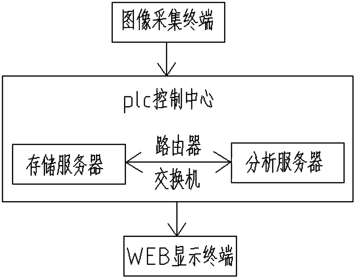
[0025] A train pantograph online detection system, such as figure 1 As shown, it includes image acquisition terminal, storage server, image analysis server, PLC control system and WEB display terminal.

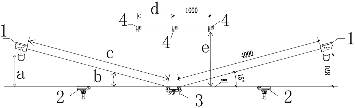
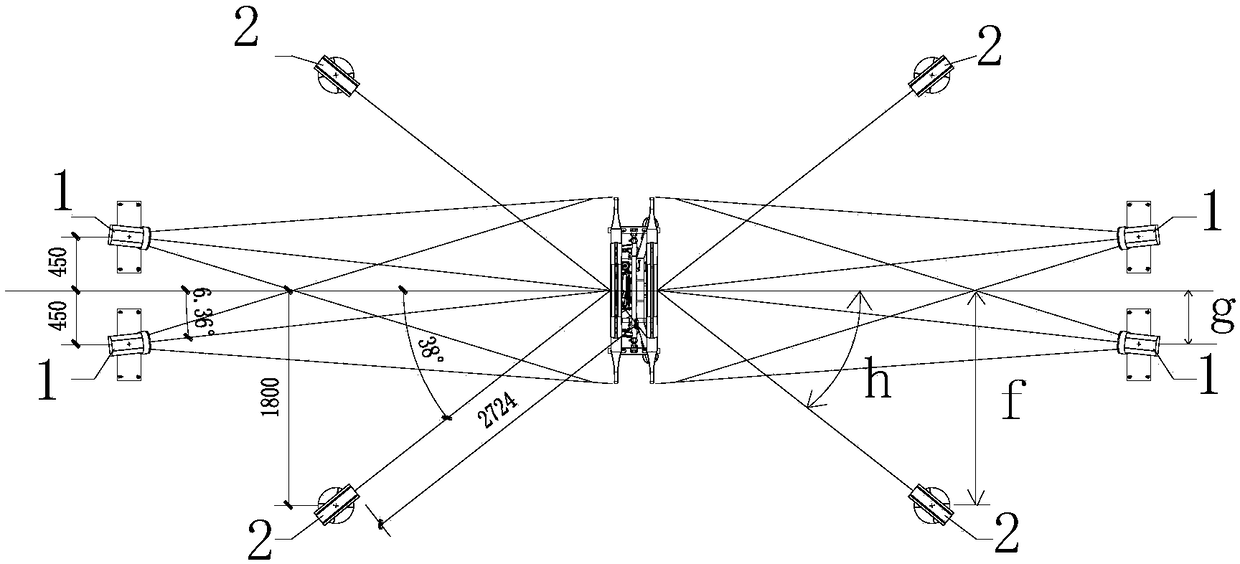
[0026] The image acquisition terminal includes two industrial cameras and a positioning sensor respectively arranged on the front and back sides of the detected pantograph, and is installed at the position below the catenary at the same height as the pantograph, and is installed on the side of the pantograph through the positioning sensor; when the train When passing, the positioning sensor signal is input to the PLC cont...


PUM


Abstract

The invention discloses an on-line detection system for a train pantograph, which comprises an image acquisition terminal, a storage server, an image analysis server, a PLC control system and a WEB display terminal, wherein the image acquisition terminal includes industrial cameras and positioning sensors arranged on the obverse and reverse sides of the detected pantograph, through the positioningsensors and is installed at the same height position as the side surface of the pantograph below an overhead line system; when a train passes by, signals of the positioning sensors are inputted intothe PLC control system to trigger the industrial cameras to collect pantograph images and transmit the collected images to the storage server; the image analysis server reads the pantograph images andanalyzes the pantograph condition through a function algorithm; and the WEB display terminal receives and feeds back information of the image analysis server. The industrial cameras collect half-pantograph images, synthesize the collected half-pantograph images into a complete pantograph image through algorithm fitting and calculate abrasion and attitude data of the pantograph. The video camerasare additionally installed on the roof to detect whether there is a foreign material or not on the roof and give an alarm. The on-line detection system is stable in image acquisition, good in imagingeffect, high in detection accuracy and stable in system operation.

Description

technical field [0001] The invention relates to the technical field of detection, in particular to an online detection system for a train pantograph. Background technique [0002] The pantograph is one of the most important parts of the train. The state of the pantograph directly affects the safety of the train. The defects of the train pantograph include pantograph wear, notch, inclination, offset, and missing horns. Defects can cause fatal injuries when trains are running and seriously affect the safety of trains. Therefore, how to detect the pantograph status of trains in real time and accurately is a technical problem that needs to be solved urgently in the development of rail transit informatization. [0003] The traditional pantograph detection method adopts manual inspection and measurement, which has a large workload, low efficiency, and requires high-altitude and power-off operations. However, the existing unmanned online detection system has disadvantages such as ...

Claims


Application Information

Patent Timeline
Patent Type & Authority Applications(China)
IPC IPC(8): G01D21/02
CPCG01D21/02
Inventor 朱晓东吕文敏董辉
Owner DONGGUAN NANNAR ELECTRONICS TECH
Why Eureka
Try Eureka