
Protection element and circuit protection device thereof

A protection component and circuit protection technology, which is applied in the direction of emergency protection devices, components of protection switches, circuits, etc., can solve the problems that the cost of the protection component 100 is not easy to further reduce, the height of the outer cover 170 is not easy to be further reduced, and it does not conform to thinning, etc. , to achieve the effect of reducing the loss of defective product scrapping, overcoming inaccurate fusing time, and reducing production costs

Active Publication Date: 2019-12-17
POLYTRONICS TECH
View PDF4 Cites 0 Cited by
  • Summary
  • Abstract
  • Description
  • Claims
  • Application Information

AI Technical Summary

Problems solved by technology

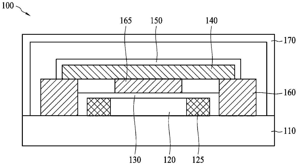
The outer cover 170 of the protective element 100 mentioned above requires a certain height to accommodate internal components, because the outer cover 170 is usually made by injection molding, and in terms of technology, it is not easy to further reduce the height of the outer cover 170, which does not meet the requirements of thinning
In addition, injection molding requires mold opening, and the cost is relatively high, making it difficult to further reduce the cost of the design of the protection element 100

Method used


Image

  • Protection element and circuit protection device thereof
  • Protection element and circuit protection device thereof
  • Protection element and circuit protection device thereof

Examples


Embodiment Construction

[0070] In order to make the above and other technical contents, features and advantages of the present invention more comprehensible, the following specifically cites relevant embodiments, together with the accompanying drawings, for a detailed description as follows.

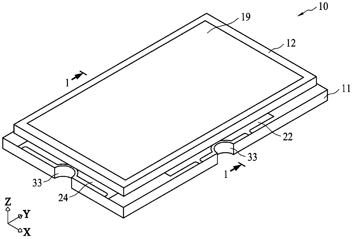
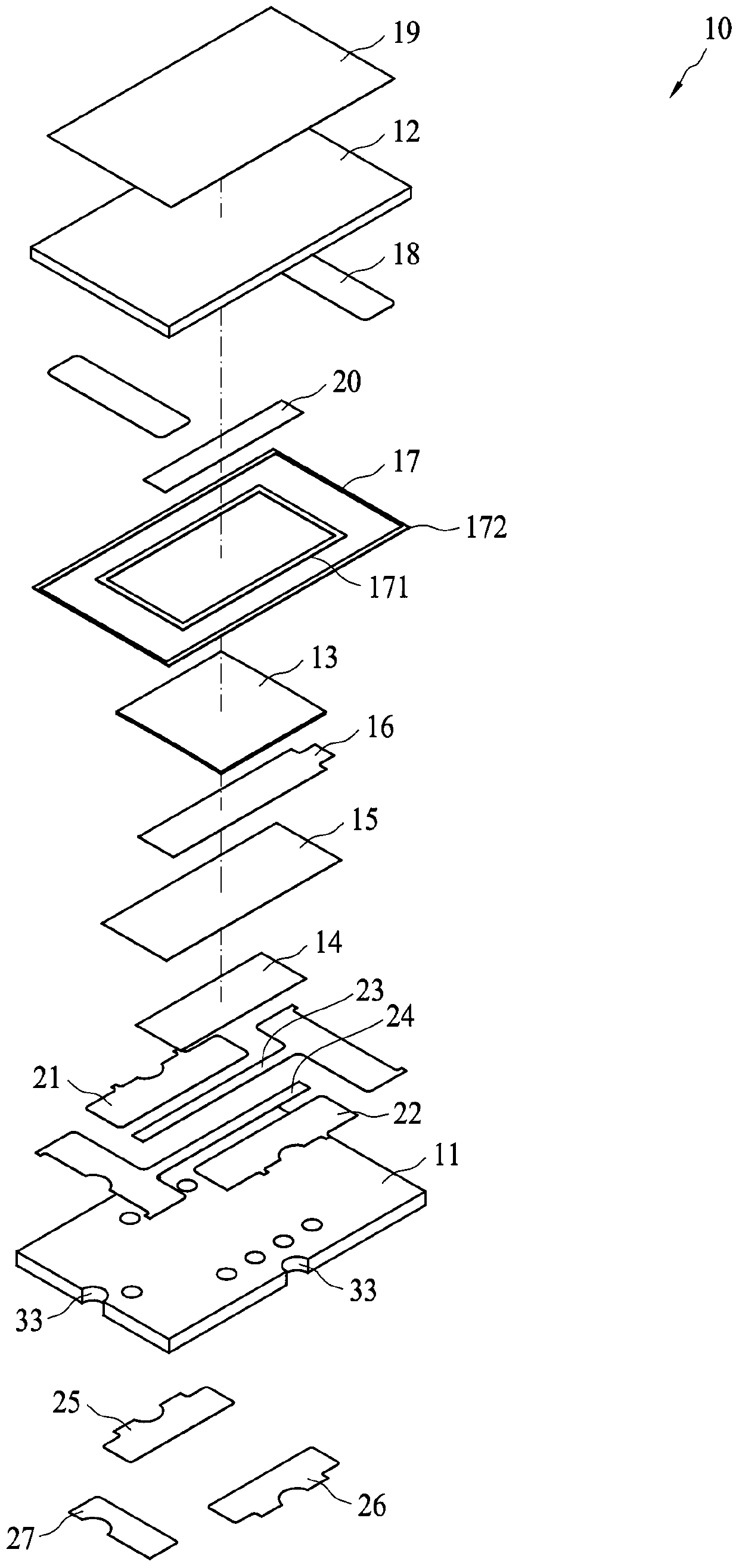
[0071] figure 2 It is a three-dimensional structure diagram of the protection element 10 according to the first embodiment of the present invention, Figure 3A is an exploded perspective view of the protection element 10, Figure 4 then figure 2 A cross-sectional view of the middle protective element 10 along the section line 1-1. The protection element 10 includes a first planar substrate 11, a second planar substrate 12, a fuse 13, a heating element 14, an insulating layer 15, an electrode layer 16, an insulating frame 17, silver glue 18, a protective layer 19, an adsorption member 20, a first Electrode 21 , second electrode 22 , third electrode 23 , fourth electrode 24 , pad 25 , pad 26 and pad 27 . Fo...


PUM


Abstract

The invention provides a protection element and a circuit protection device thereof. The protective element includes a first planar substrate, a second planar substrate, a heating member, a fuse member, and an adsorption member. The first planar substrate includes a first surface and the second planar substrate includes a second surface facing the first surface. The heating member is arranged on the first surface, and the fuse member is arranged above the heating member. The adsorption member is arranged on the second surface and is positioned above the fuse. When an overvoltage or an over temperature occurs, the heating element heats to melt the fuse, and the adsorption element adsorbs molten metal of the fuse.

Description

technical field [0001] The invention relates to a protection element applied in an electronic device and a circuit protection device including the protection element, in particular to a protection element with the function of preventing overvoltage, overcurrent or overtemperature and a circuit protection device thereof. Background technique [0002] As a conventional overcurrent protection element, a current fuse made of a low-melting-point metal such as lead, tin, and antimony is widely known. Afterwards, in terms of preventing overcurrent and overvoltage, protection elements were continuously developed, which included sequentially stacking a heat generating layer and a low-melting point metal layer on a flat substrate. When the overvoltage occurs, the heating body generates heat, and the heat is transferred upward from the bottom to heat the electrode carrying the low-melting-point metal body, thereby fusing the low-melting-point metal body and cutting off the flowing curr...

Claims


Application Information

Patent Timeline
Patent Type & Authority Patents(China)
IPC IPC(8): H01H71/12H01H85/046
CPCH01H71/122H01H85/046
Inventor 苏聪敏蔡东成王绍裘
Owner POLYTRONICS TECH
Learn More