
A power device

A technology of power devices and curvature, applied in semiconductor devices, electrical components, circuits, etc., can solve problems such as waste

Active Publication Date: 2018-12-11
郯城县新区建设发展有限公司
View PDF6 Cites 3 Cited by
  • Summary
  • Abstract
  • Description
  • Claims
  • Application Information

AI Technical Summary

Problems solved by technology

Therefore, when designing the voltage divider ring of the device, a larger curvature radius is usually set at the corner of the voltage divider ring in order to obtain a better curvature of the electric field and reduce the breakdown electric field, thereby increasing the breakdown voltage of the device as a whole. The greater the radius of curvature, the greater the ratio of the chip area occupied by the pressure divider ring, especially for right-angle scribing lanes, the waste of corner area is inevitable

Method used

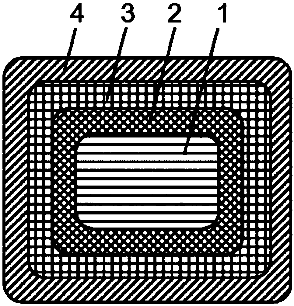

Image

  • A power device
  • A power device
  • A power device

Examples


Embodiment Construction

[0011] In order to make the objectives, technical solutions and beneficial technical effects of the present invention clearer, the technical solutions in the embodiments of the present invention will be clearly and completely described below in conjunction with the drawings in the embodiments of the present invention. Obviously, the described implementation Examples are only some embodiments of the present invention, not all embodiments. Based on the embodiments of the present invention, all other embodiments obtained by persons of ordinary skill in the art without making creative efforts belong to the protection scope of the present invention.

[0012] It should be noted that, in the case of no conflict, the embodiments of the present invention and the features in the embodiments can be combined with each other.

[0013] In describing the present invention, it should be understood that the terms "center", "longitudinal", "transverse", "upper", "lower", "front", "rear", "left"...


PUM


Abstract

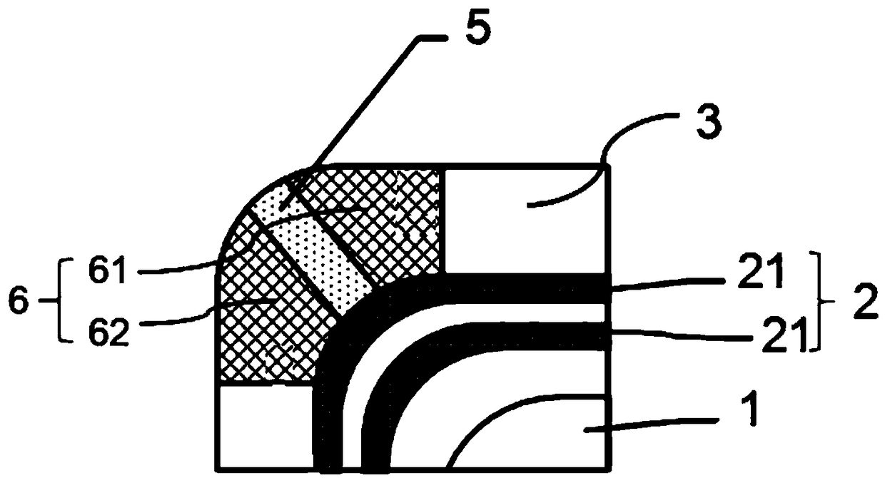
The invention relates to apower device including the active area, a voltage sharing region and a cut-off ring region, the voltage sharing region comprising at least one voltage sharing ring of a firstconductivity type, A cut-off re region is arranged at that periphery of the voltage sharing ring, the voltage sharing ring having at least one corner, the cut-off ring region having at least one outer corner corresponding one-to-one to a corner of the voltage sharing ring, A super junction structure is for in that cut-off ring region, the super junction structure includes a first injection regionof a first conductivity type and a second injection region of a second conductivity type, the first injection region extends from a peripheral corner of the voltage sharing ring to a corresponding corner of the cut-off ring region, The second injection region includes a first portion formed on both sides of the first injection region and connected to the first injection region, and a second portion formed on both sides of the first injection region. One end of the first injection region and the second injection region jointly cover a corner region of the first voltage sharing ring.

Description

technical field [0001] The invention relates to the technical field of semiconductors, in particular to a power device. Background technique [0002] In the practical application of power devices, when they are under reverse bias, the voltage is mainly borne by the voltage divider ring. Since the voltage divider ring has a ring structure, the place where the actual electric field is strongest is located at the corner of the voltage divider ring. Therefore, when designing the voltage divider ring of the device, a larger curvature radius is usually set at the corner of the voltage divider ring in order to obtain a better curvature of the electric field and reduce the breakdown electric field, thereby increasing the breakdown voltage of the device as a whole. The greater the radius of curvature, the greater the ratio of the chip area occupied by the pressure divider ring, especially for right-angle scribing lanes, the waste of corner area is inevitable. Contents of the invent...

Claims


Application Information

Patent Timeline
Patent Type & Authority Applications(China)
IPC IPC(8): H01L29/06
Inventor 王永贵阳林涛邱一平
Owner 郯城县新区建设发展有限公司
Learn More