A high-heat-dissipating air-type bus duct and a preparation method thereof
A technology of high heat dissipation and busway, applied in the direction of electrical components, etc., can solve the problems of affecting the service life of the busbar, low heat dissipation efficiency, high ambient temperature, etc., and achieve the effect of improving insulation effect, improving heat dissipation efficiency, and good permeability resistance
- Summary
- Abstract
- Description
- Claims
- Application Information
AI Technical Summary
Problems solved by technology
Method used
Image
Examples
Embodiment 1
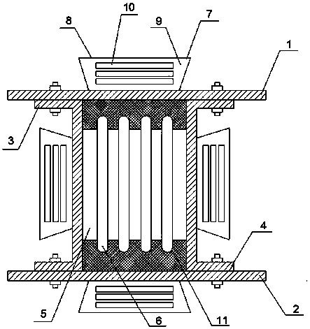
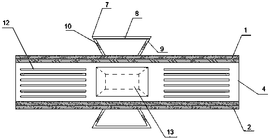
[0032] This embodiment provides a high heat dissipation air type bus duct, including an upper cover 1, a lower cover 2, a left side 3 and a right side 4, an upper cover 1, a lower cover 2, and a left side 3 And the right side plate 4 encloses a wire chamber 5, a busbar 6 is installed in the wire chamber 5, and an insulating partition 11 is arranged between the busbar 6, the upper cover plate 1, and the lower cover plate 2. A rectangular through hole 13 is provided on the upper cover plate 1, the lower cover plate 2, the left side plate 3 and the right side plate 4, and a heat dissipation cavity 7 is arranged on each rectangular through hole 13, and the heat dissipation cavity 7 is formed by the top plate 8. Surrounded by four connecting plates 9, the top plate 8 is also rectangular, and the four connecting plates 9 connect the rectangular through hole 13 with the top plate 8, so that the heat dissipation chamber 7 communicates with the line chamber 5.
[0033] Wherein, the len...
Embodiment 2
[0043]This embodiment provides a high heat dissipation air type bus duct, including an upper cover 1, a lower cover 2, a left side 3 and a right side 4, an upper cover 1, a lower cover 2, and a left side 3 And the right side plate 4 encloses a wire chamber 5, a busbar 6 is installed in the wire chamber 5, and an insulating partition 11 is arranged between the busbar 6, the upper cover plate 1, and the lower cover plate 2. A rectangular through hole 13 is provided on the upper cover plate 1, the lower cover plate 2, the left side plate 3 and the right side plate 4, and a heat dissipation cavity 7 is arranged on each rectangular through hole 13, and the heat dissipation cavity 7 is formed by the top plate 8. Surrounded by four connecting plates 9, the top plate 8 is also rectangular, and the four connecting plates 9 connect the rectangular through hole 13 with the top plate 8, so that the heat dissipation chamber 7 communicates with the line chamber 5.
[0044] Wherein, the leng...
Embodiment 3
[0054] This embodiment provides a high heat dissipation air type bus duct, including an upper cover 1, a lower cover 2, a left side 3 and a right side 4, an upper cover 1, a lower cover 2, and a left side 3 And the right side plate 4 encloses a wire chamber 5, a busbar 6 is installed in the wire chamber 5, and an insulating partition 11 is arranged between the busbar 6, the upper cover plate 1, and the lower cover plate 2. A rectangular through hole 13 is provided on the upper cover plate 1, the lower cover plate 2, the left side plate 3 and the right side plate 4, and a heat dissipation cavity 7 is arranged on each rectangular through hole 13, and the heat dissipation cavity 7 is formed by the top plate 8. Surrounded by four connecting plates 9, the top plate 8 is also rectangular, and the four connecting plates 9 connect the rectangular through hole 13 with the top plate 8, so that the heat dissipation chamber 7 communicates with the line chamber 5.
[0055] Wherein, the len...
PUM
 Abstract
Description
Claims
Application Information
 - R&D
- Intellectual Property
- Life Sciences
- Materials
- Tech Scout
- Unparalleled Data Quality
- Higher Quality Content
- 60% Fewer Hallucinations
Browse by: Latest US Patents, China's latest patents, Technical Efficacy Thesaurus, Application Domain, Technology Topic, Popular Technical Reports.
© 2025 PatSnap. All rights reserved.Legal|Privacy policy|Modern Slavery Act Transparency Statement|Sitemap|About US| Contact US: help@patsnap.com


