Painting robot arm device

A robot arm and rotating device technology, which is applied to spray devices, manipulators, manufacturing tools, etc., can solve the problems of no pneumatic lifting device, low work efficiency, and inaccurate painting operations, so as to avoid uneven painting and fine painting operations. , Use a wide range of effects

Inactive Publication Date: 2018-12-14
SUZHOU HONGMIAO INTELLIGENT TECH CO LTD
View PDF0 Cites 5 Cited by
  • Summary
  • Abstract
  • Description
  • Claims
  • Application Information

AI Technical Summary

Problems solved by technology

However, manual spraying is time-consuming and laborious, it is difficult to control the quality of spraying, and it is prone to danger and low work efficiency. Most of the mechanical spraying uses large spraying machines, which are expensive, inconvenient to move, and take up a lot of space
[0003] At present, the robot arm is the most widely used automatic mechanical device in the field of robot technology. With the continuous development of the industrialized society, the demand for the robot arm continues to increase, and the same is true for the painting processing industry. However, the currently sold painting robot arms still exist. Some more or less deficiencies affect its use, such as no pneumatic lifting device, the processing operation is limited by the volume of the object, the operating range is relatively narrow, the invention is not high, there is no rotating device, and the angle of the nozzle cannot be fine-tuned. The adjustment of the paint job is not fine, the painting effect is relatively poor, etc.

Method used


Image

  • Painting robot arm device
  • Painting robot arm device

Examples


Embodiment Construction

[0015] The following will clearly and completely describe the technical solutions in the embodiments of the present invention with reference to the accompanying drawings in the embodiments of the present invention. Obviously, the described embodiments are only some, not all, embodiments of the present invention. Based on the embodiments of the present invention, all other embodiments obtained by persons of ordinary skill in the art without making creative efforts belong to the protection scope of the present invention.

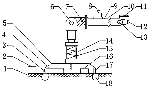
[0016] see figure 1 , figure 1 It is a structural schematic diagram of the present invention; a painting robot arm device, including a base 1, a casing 5 and a cylinder 14, the lower part of the base 1 is connected with a universal wheel 18 through a bearing, and the upper part of the base 1 is fixed with a counterweight by welding Block 2, the upper part of the base 1 is fixed with an organic casing 5 by welding, an air pump 4 is installed inside the casing ...


PUM


Abstract

The invention discloses a painting robot arm device. The painting robot arm device comprises a base, a casing and an air cylinder; the lower portion of the base is connected with universal wheels through bearings; a balancing weight is welded and fixed to the upper portion of the base; the casing is welded and fixed to the upper portion of the base; an air pump is mounted in the casing; an air inlet is mounted on the left portion of the air pump; a processor is mounted on the side, away from the balancing weight, of the air pump; an operation panel is mounted on the left side of the processor;the air cylinder is mounted on the upper portion of the casing; a telescopic spring is mounted in the air cylinder; a rotator is mounted on the upper portion of the air cylinder; a driving motor is mounted on the right side of the rotator; a horizontal pipe is mounted on the right side of the driving motor; the upper portion of the horizontal pipe is provided with a paint inlet pipe; and an adjustment knob is mounted on the right side of the paint inlet pipe. Operation of the device is not limited by the volume, the application range is wide, the rotator is arranged, the angle of a nozzle canbe finely adjusted, the painting effect is good, and the painting operation efficiency is improved.

Description

technical field [0001] The invention belongs to the technical field of mechanical spraying, and in particular relates to a painting robot arm device. Background technique [0002] As we all know, with the continuous development of the die casting industry, there are higher requirements for the efficiency and quality of the production of die castings. In order to improve the corrosion resistance and aesthetics of the produced die castings, the existing technology generally sprays the surface of the die castings Various coatings are used to achieve anti-corrosion and beautifying effects. However, manual spraying is time-consuming and laborious, it is difficult to control the quality of spraying, and it is prone to danger and low work efficiency. Most of the mechanical spraying uses large spraying machines, which are expensive, inconvenient to move, and take up a lot of space. [0003] At present, the robot arm is the most widely used automatic mechanical device in the field o...

Claims


Application Information

Patent Timeline
Patent Type & Authority Applications(China)
IPC IPC(8): B05B13/04B05B15/625B05B15/68B25J11/00
CPCB05B13/0431B05B15/625B05B15/68B25J11/0075
Inventor 潘楚骁
Owner SUZHOU HONGMIAO INTELLIGENT TECH CO LTD
Why Eureka
Try Eureka