Eureka AIR delivers breakthrough ideas for toughest innovation challenges, trusted by R&D personnel around the world.

Internal mixer with dust-sucking and cooling device

The technology of a cooling device and an internal mixer, which is applied in the field of internal mixers, can solve the problems of poor discharge quality, early discharge, and unlocked discharge doors, so as to improve the discharge quality and avoid burning.

Active Publication Date: 2018-12-14
沧州启航橡胶制品有限公司
View PDF7 Cites 8 Cited by
  • Summary
  • Abstract
  • Description
  • Claims
  • Application Information

AI Technical Summary

Problems solved by technology

[0003] However, the discharge quality of the existing internal mixer during the discharge process is poor, and it is easy to damage the rubber material due to the excessive pressure of the top bolt and the unfixed position when moving. The device drives the unloading door to open to realize unloading, but at the moment when unloading starts, the lower jacking bolt is under greater pressure, which is likely to cause damage to the unloading device, and when the unloading door is closed after unloading, it is easy to be unlocked and discharge in advance. However, when the material is unloaded, the temperature is very high and there is a lot of dust attached, which will make the subsequent transportation inconvenient, and the dust will also pollute the environment. The conventional dust collection and cooling methods are complicated and inefficient.

Method used


Image

  • Internal mixer with dust-sucking and cooling device
  • Internal mixer with dust-sucking and cooling device
  • Internal mixer with dust-sucking and cooling device

Examples


Embodiment Construction

[0028] The following will clearly and completely describe the technical solutions in the embodiments of the present invention with reference to the accompanying drawings in the embodiments of the present invention. Obviously, the described embodiments are only some, not all, embodiments of the present invention. Based on the embodiments of the present invention, all other embodiments obtained by persons of ordinary skill in the art without making creative efforts belong to the protection scope of the present invention.

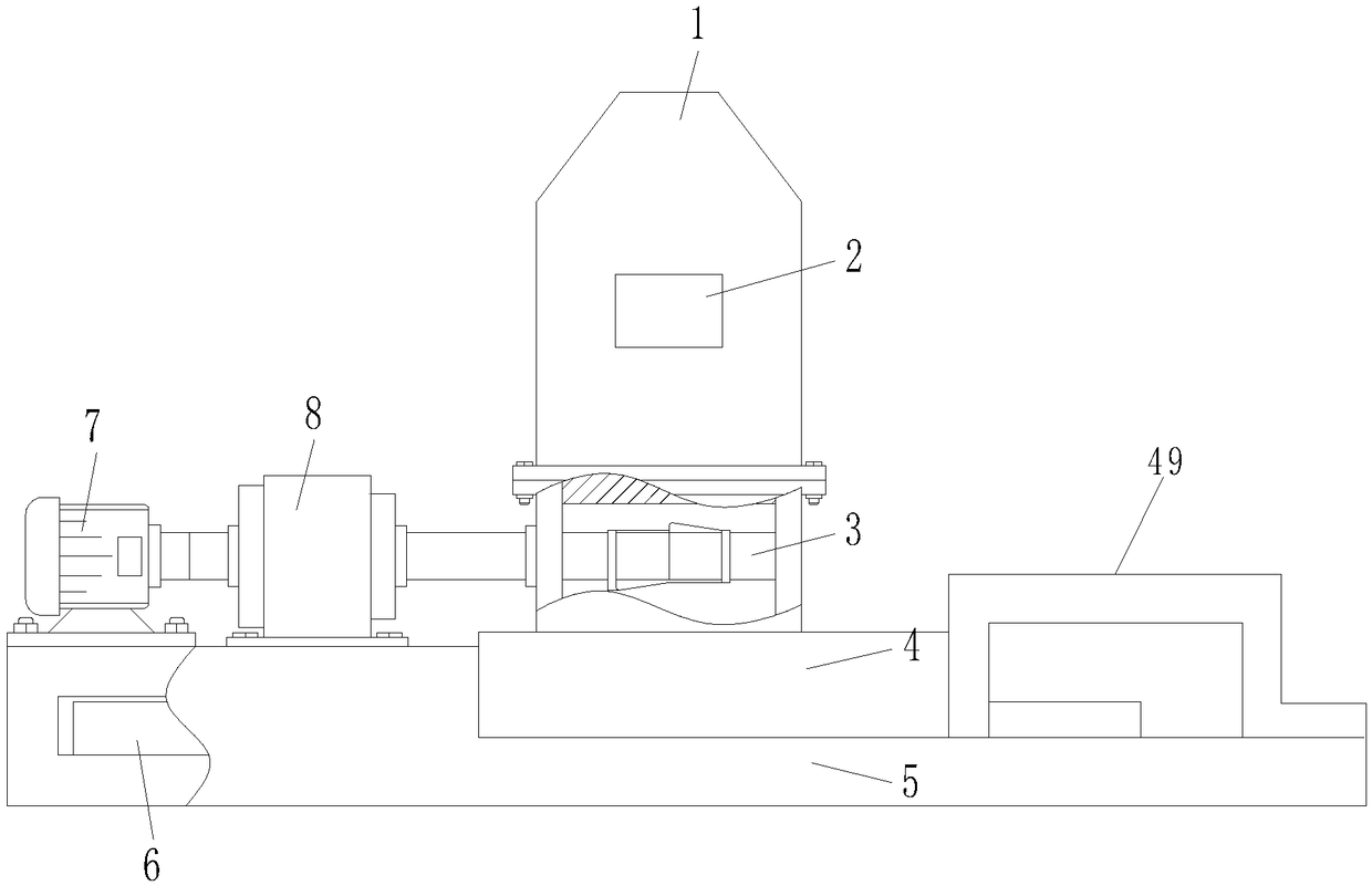
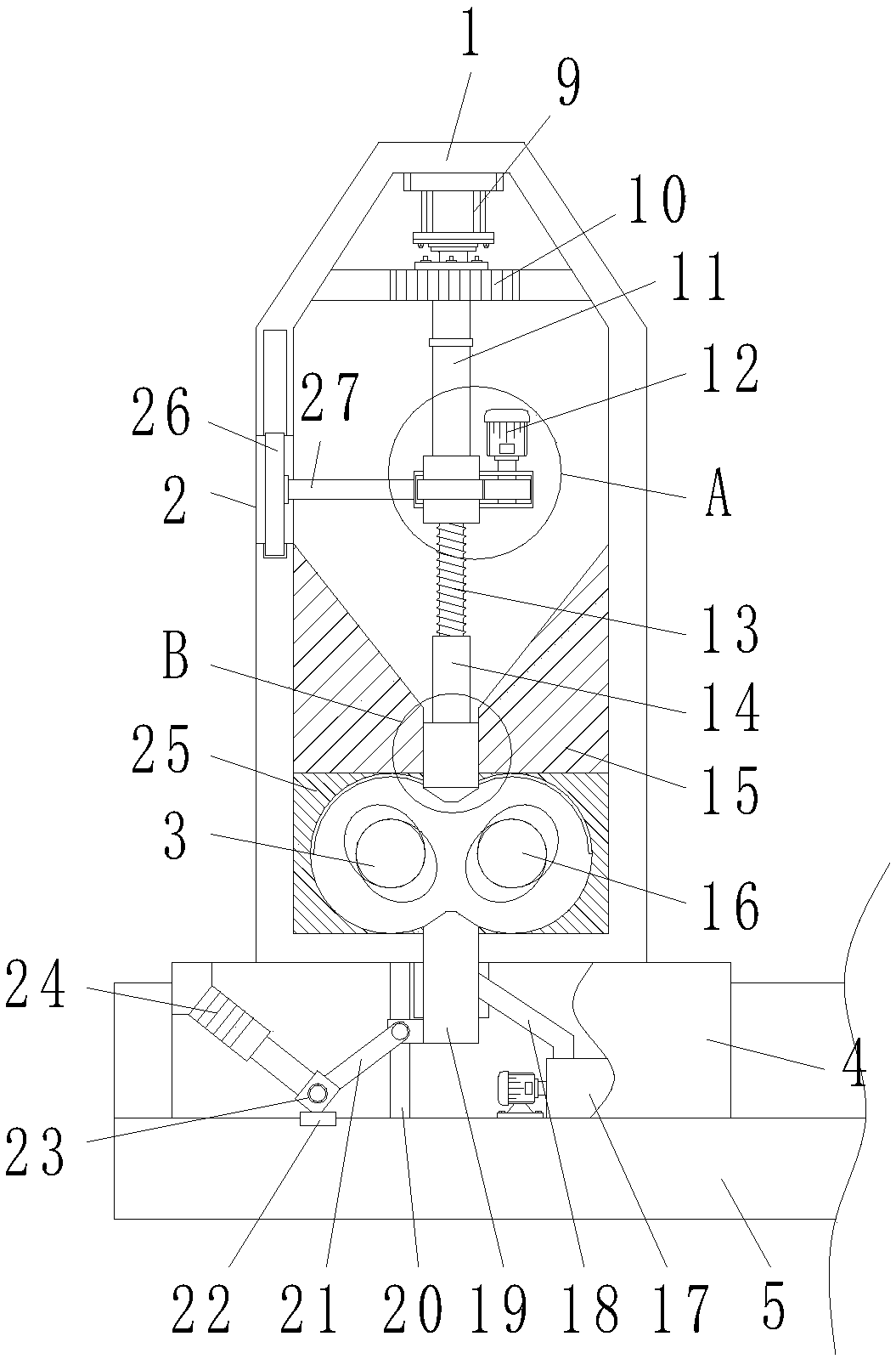
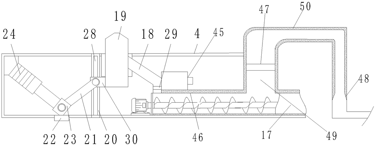
[0029] see Figure 1-8, the present invention provides the following technical scheme: a kind of internal mixer with vacuum cooling device, comprising internal mixer body 1, one side outer wall of internal mixer body 1 is provided with feed inlet 2, and internal mixer body 1 The lower hopper 15 and the mixing chamber 25 are installed inside, the lower hopper 15 is located above the mixing chamber 25, and the upper top bolt 43 is installed in the middle of the ...


PUM


Abstract

The invention discloses an internal mixer with a dust-sucking and cooling device. The internal mixer comprises an internal mixer body; a feeding port is formed in the outer wall of one side of the internal mixer body; a feeding hopper and a mixing chamber are arranged in the internal mixer body; the feeding hopper is positioned above the mixing chamber; an upper top bolt is arranged in the middleposition of the feeding hopper; the internal mixer is provided with a second motor, a screw rod, a second guide rod, a fixed base, a driving gear, a driven gear, a screw rod sleeve, a water pump, a dust-sucking pipeline, a centripetal annular spray head and a side wall; during unloading, a PLC controller controls a first motor to start to work, the first motor drives the driving gear through a rotating shaft to rotate, the driving gear is engaged with the driven gear, the driven gear drives the screw rod sleeve to rotate, and the screw rod sleeve is screwed with the screw rod when rotating, sothat the aim of ascending the screw rod is fulfilled, and the second guide rod drives the upper top bolt to move upwards when the screw rod ascends until one end of the second guide rod is contactedwith the screw rod sleeve; the upper top bolt is started in the unloading process, so that the discharging pressure of a lower top bolt can be reduced; in addition, when an adhesive material is cooled, dust is removed and the removed dust is fused into water for cooling, so that the processes are reduced and environmental friendliness is achieved.

Description

technical field [0001] The invention belongs to the technical field of internal mixers, and in particular relates to an internal mixer with a dust suction cooling device. Background technique [0002] Closed rubber mixing machine is referred to as internal mixer, also known as kneader, which is mainly used for plasticizing and mixing of rubber. Internal mixer is a kind of rotor with a pair of specific shapes and relative rotation. The temperature and pressure can be adjusted. It is a machine for plasticizing and kneading polymer materials intermittently in a closed state. It is mainly composed of a mixing chamber, a rotor, a rotor sealing device, a feeding and pressing device, a discharging device, a transmission device and a machine base. [0003] However, the discharge quality of the existing internal mixer during the discharge process is poor, and it is easy to damage the rubber material due to the excessive pressure of the top bolt and the unfixed position when moving. ...

Claims


Application Information

Patent Timeline
Patent Type & Authority Applications(China)
IPC IPC(8): B29B7/26B29B7/18B29B7/80B29B7/82B08B15/04B01D47/06
CPCB01D47/06B08B15/04B29B7/18B29B7/26B29B7/80B29B7/826B29B7/183B29B7/263B29B7/7495B29B7/801B29B7/86
Inventor 艾蒙雁
Owner 沧州启航橡胶制品有限公司
Why Eureka
Eureka Blog
Learn More