Distortion compensating circuit, receiver, base station and radio communication system

A distortion compensation and circuit technology, applied in the field of optical communication and nonlinear distortion compensation, can solve the problems of low precision and increased circuit scale of radio base stations.

Inactive Publication Date: 2002-08-28
NIPPON TELEGRAPH & TELEPHONE CORP
View PDF2 Cites 0 Cited by
  • Summary
  • Abstract
  • Description
  • Claims
  • Application Information

AI Technical Summary

Problems solved by technology

However, the control methods so far are controlled by the disturbance method, and the precision is very low.
[0006] In order to perform nonlinear distortion compensation using the predistortion method at the transmitting end, when perfo...

Method used


Image

  • Distortion compensating circuit, receiver, base station and radio communication system
  • Distortion compensating circuit, receiver, base station and radio communication system
  • Distortion compensating circuit, receiver, base station and radio communication system

Examples


no. 1 Embodiment

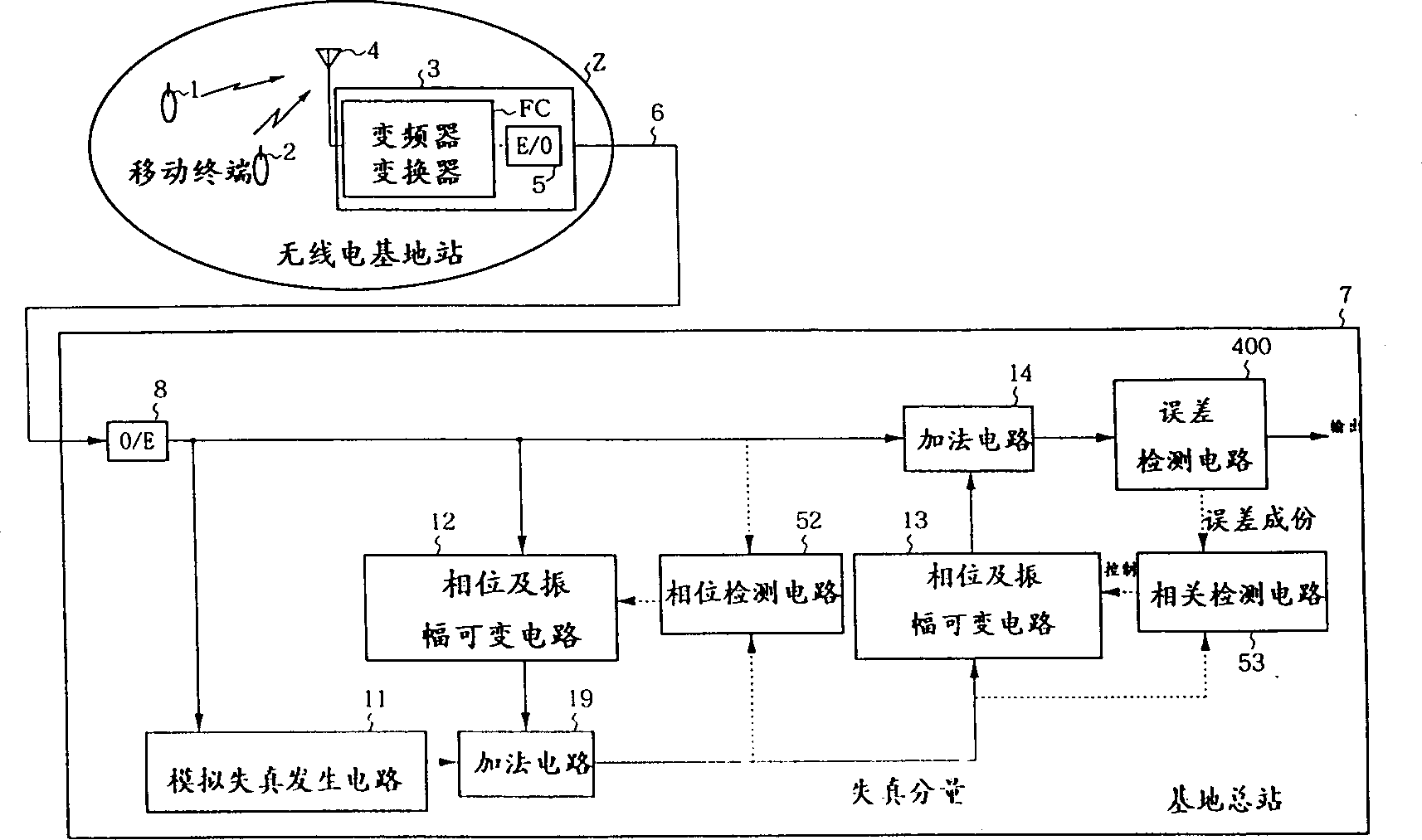
[0029] The configuration of the first embodiment of the present invention will be described with reference to FIG. 2 . Fig. 2 is a structural block diagram of the device according to the first embodiment of the present invention.

[0030] The device of the first embodiment of the present invention is equipped with an intermediate frequency signal containing odd-order distortion through digital multiple quadrature phase modulation as an input and divides the intermediate frequency signal into two dividers 9; one output of the divider 9 is divided into two Two-way distributor 10; make one output of this distributor 10 pass through and the analog distortion generating circuit 11 set equivalently with the generation cause of above-mentioned odd order distortion; Change circuit 12; The output of this phase and amplitude variable circuit 12 and the output of analog distortion generation circuit 11 actually carry out the addition circuit 19 of subtraction operation; The phase and amp...

no. 2 Embodiment

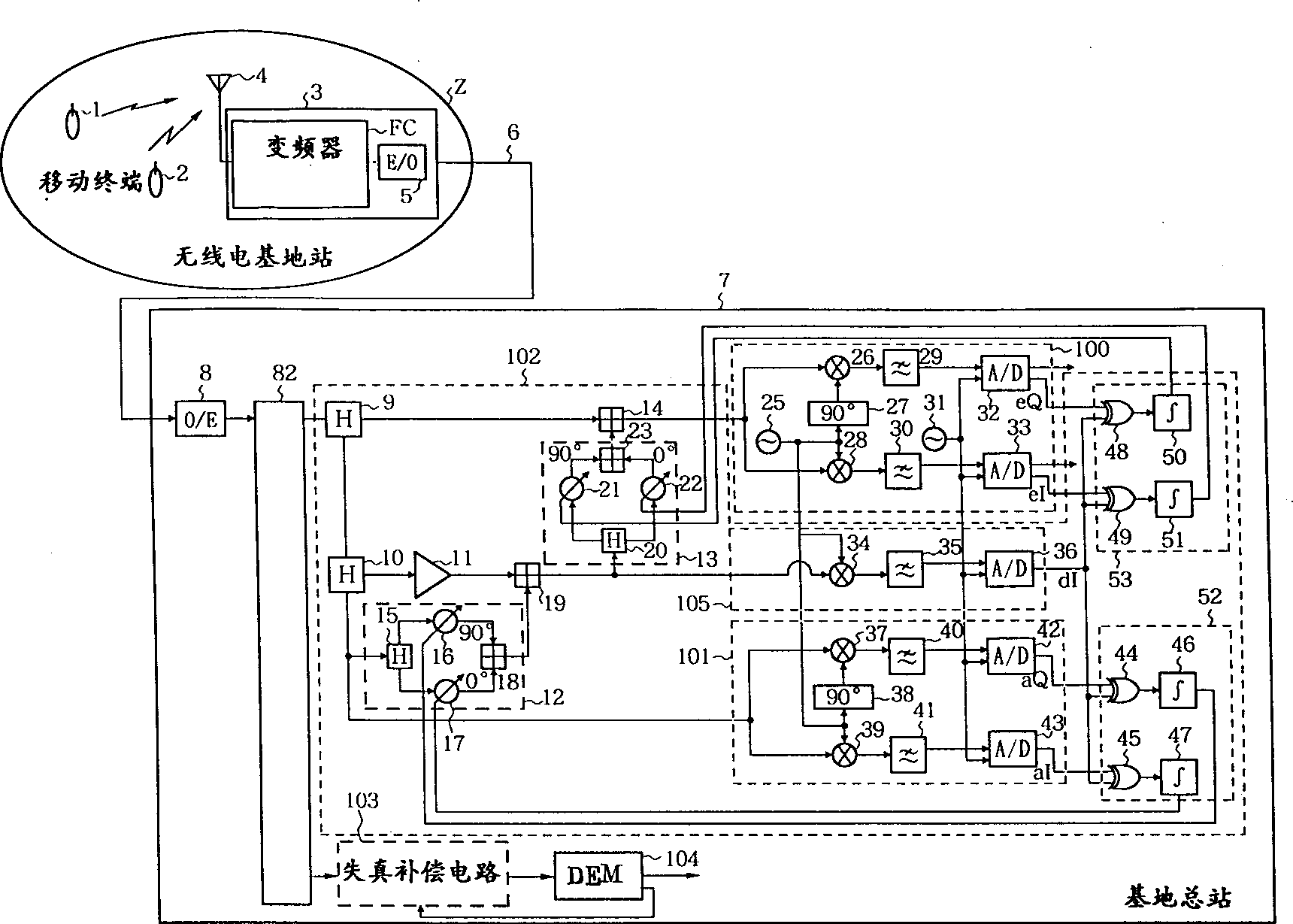
[0046] Next, a second embodiment of the present invention will be described with reference to FIG. 6 . Fig. 6 is a block diagram showing the structure of the device according to the second embodiment of the present invention. The main difference between the second embodiment of the present invention and the first embodiment of the present invention is that in the first embodiment of the present invention, in the part where the phase and amplitude variable circuits 12 and 13 are used, an IF with multiple taps is used. The operating two-dimensional transversal filters 12' and 13' are controlled by correlation detection circuits 52' and 53'. In the second embodiment of the present invention, the compensation is set in consideration of the frequency characteristics of the broadband main signal and the distortion component.

[0047] Fig. 7 is a block diagram showing the configuration of transversal filters 12' and 13' (in the case of three taps). The transversal filters 12' and 1...

no. 3 Embodiment

[0052] Next, a third embodiment of the present invention will be described with reference to FIG. 9 . Fig. 9 is a block diagram showing the structure of the device according to the third embodiment of the present invention. The difference between the third embodiment of the present invention and the first embodiment or the second embodiment of the present invention is that the divider 71 is arranged in the front stage of the filter 82 for demultiplexing, and the demultiplexing filter 72 for analog distortion divides the The path of the phase demodulation circuit 100 corresponding to the mobile terminal 1 and the path of the phase demodulation circuit 104 corresponding to the mobile terminal 2 are distributed to the signal after the analog distortion is added by the analog distortion generation circuit 11 through the circuit breaker 71 . In the first or second embodiment of the present invention, distortion is generated in two paths, but by adopting the structure of the third e...


PUM


Abstract

In order to perform distortion compensation control with high precision, the present invention divides the received signal into two systems, makes the first signal in the two systems pass through a distortion generator with the same distortion characteristics as that generated at the transmitting end, and controls the distortion of the second signal Phase and amplitude, by adding the two signals, the main signal is suppressed and only the distortion component is extracted. Next, the phase and amplitude of the extracted distortion components are controlled and added to the second signal to remove the distortion components contained in the second signal. Therefore, it is possible to miniaturize the transmitting device that compensates the distortion generated at the transmitting end at the receiving end.

Description

technical field [0001] The invention relates to nonlinear distortion compensation in communication transmission lines. The present invention is suitable for optical communication, and also suitable for mobile communication. Background technique [0002] A conventionally known technique for compensating nonlinear distortion includes a predistortion method. Now refer to Figure 16 This conventional example will be described. Figure 16 It is a structural block diagram of the original example device. Such as Figure 16 As shown in the structure, the radio base station 3 installed in the radio signal area Z receives the radio signals from the mobile terminals 1 and 2, converts them into optical signals, and transmits them to the main base station 7 through the optical fiber transmission line 6. In this access method, the non-linear distortion generated in the electro-optical converter 5 of the radio base station 3 is compensated by a predistortion method. [0003] exist Figu...

Claims


Application Information

Patent Timeline
IPC IPC(8): H03F1/32
CPCH03F1/3223
Inventor 上野众太渡边和二
Owner NIPPON TELEGRAPH & TELEPHONE CORP
Why Eureka
Try Eureka