Pile foundation anti-pulling detection device convenient in fixing and application method thereof

A detection device and pile foundation technology, which can be used in basic structure engineering, basic structure test, construction, etc., can solve the problems of instability, easy falling and fixing, etc., achieve stable clamping, ensure accuracy, and increase contact area Effect

Inactive Publication Date: 2018-12-14
苏州市三联建设工程勘测有限公司
View PDF4 Cites 3 Cited by
  • Summary
  • Abstract
  • Description
  • Claims
  • Application Information

AI Technical Summary

Problems solved by technology

However, during the fixing process, the pile foundation is fixed only by the left and right jaws on both sides and the anti-skid teeth on the jaws. This fixing method is easy to fall during use and cause insufficiency in fixing. stable situation occurs

Method used


Image

  • Pile foundation anti-pulling detection device convenient in fixing and application method thereof
  • Pile foundation anti-pulling detection device convenient in fixing and application method thereof
  • Pile foundation anti-pulling detection device convenient in fixing and application method thereof

Examples


Embodiment 1

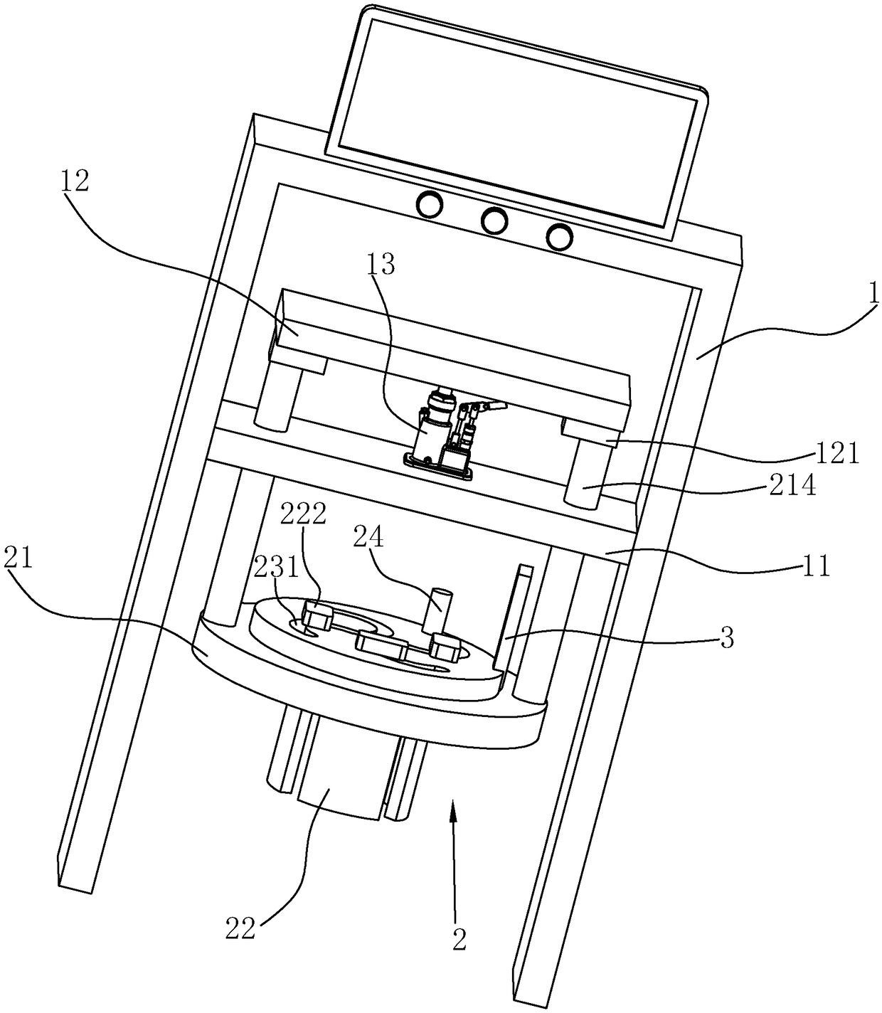
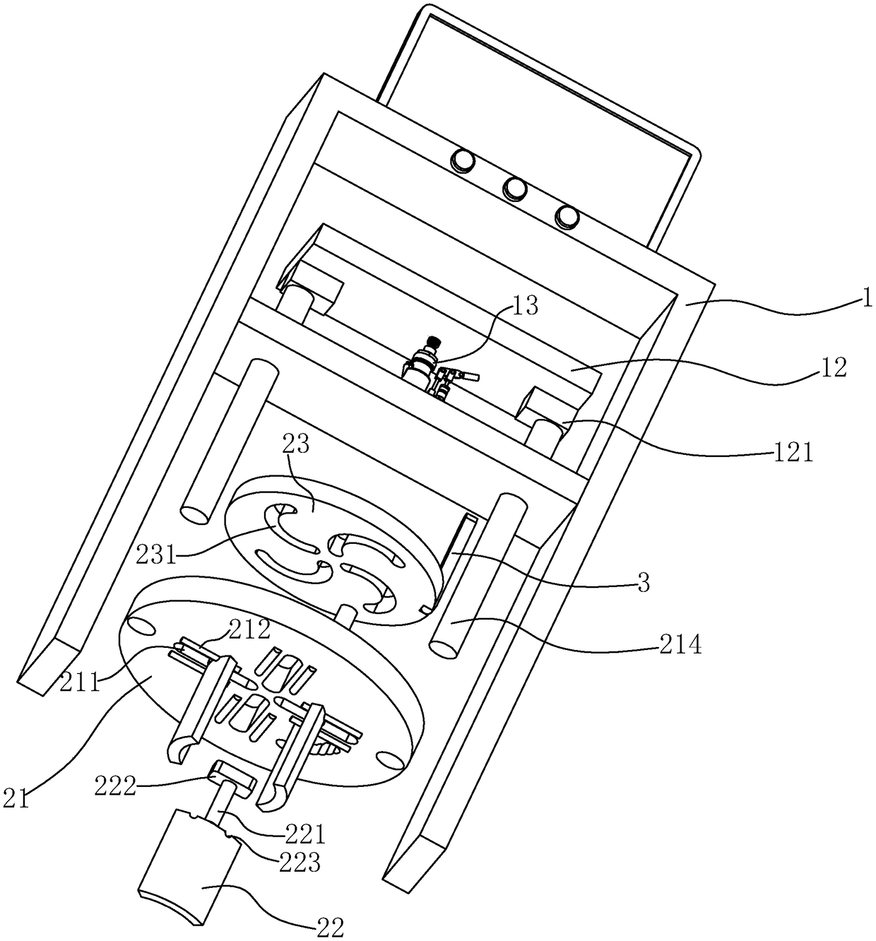
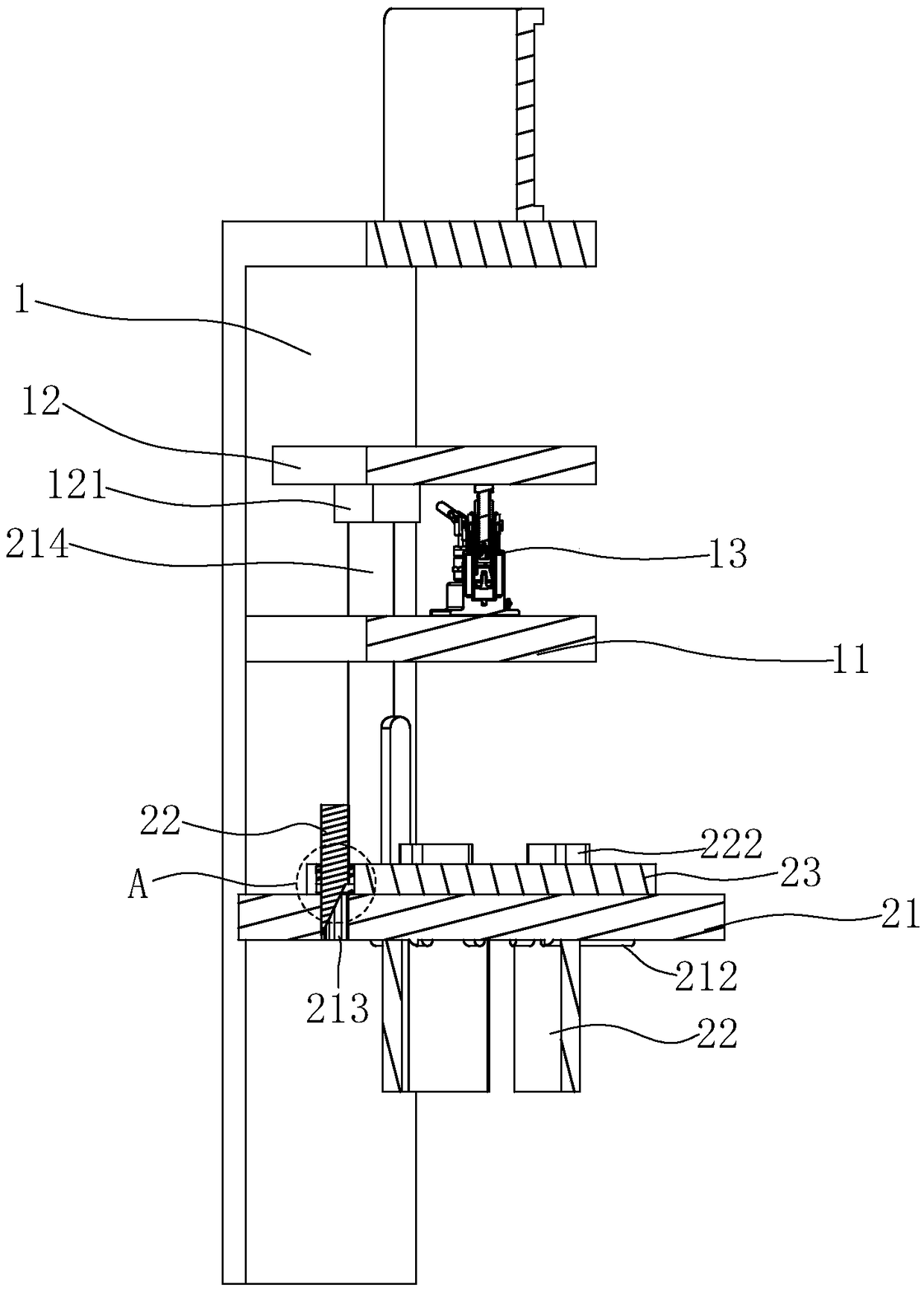
[0041] A convenient and fixed pile foundation pullout detection device, such as figure 1As shown, it includes an outer bracket 1 and a clamping device 2. Here, the bracket 1 is provided with a horizontal support plate 11 above the clamping device 2. The horizontal support plate 11 is provided with a jack 13 and a balance plate 12, and this embodiment In the example, the balance plate 12 is connected to the clamping device 2 through the guide rod 214, and the pressure sensor 121 is installed at the bottom of the balance plate 12; figure 1 As shown, the clamping device 2 includes a top plate 21 located at the top, and in this embodiment, the top plate 21 is fixedly connected with the guide rod 214, and a plurality of abutment plates 22 are arranged under the top plate 21 to surround the outer periphery of the pile foundation. In the example, the number of abutting plates 22 is set to four, the abutting plates 22 and the top plate 21 are connected to each other, and in this embod...

Embodiment 2

[0049] A method of using a pile foundation uplift detection device, which is mainly used for a convenient and fixed pile foundation uplift detection device proposed in Embodiment 1, and the steps are as follows:

[0050] S1: Abut the top plate 21 on the top of the pile foundation, and adjust the bracket 1 so that the horizontal support plate 11 is placed horizontally.

[0051] By placing the horizontal support plate 11 horizontally, in the later detection process, the force balance on the top surface of the pile foundation is ensured, so that the detection result can be more accurate.

[0052] S2: Adjust the fixing plate 23 by adjusting the handle 3 to make it rotate, so that the slider 221 located in the adjusting groove 231 slides to the center of the top plate 21, so that the abutting plate 22 can abut the outside of the pile foundation. In this way, by adjusting the handle 3, the fixing plate 23 can be adjusted more conveniently, thereby realizing the adjustment of the pos...


PUM


Abstract

The invention provides a pile foundation anti-pulling detection device convenient in fixing and an application method thereof, and relates to the technical field of the design of a pile foundation detection device. The technical problem that a pile foundation is clamped unstably in the detection process is solved. The pile foundation anti-pulling detection device comprises a support on the outer side and a clamping device, wherein the clamping device comprises a top plate positioned at the top, and the top plate is fixedly connected with a guide rod. A plurality of abutting plates arranged onthe periphery of the pile foundation in a surrounded mode are arranged under the top plate, and the abutting plates are mutually connected with the top plate. The top plate is circularly arranged, andthe abutting plates slide along the radius direction of the top plate. By the abutting plates arranged on the periphery of the pile foundation in the surrounded mode, the contact area between the clamping device and the pile foundation is increased, and therefore the clamping device can more stably clamp the pile foundation. In the detection process, falling out between the clamping device and the pile foundation can be effectively avoided, and the accuracy of a final detection structure is ensured.

Description

technical field [0001] The invention relates to the technical field of pile foundation detection device design, in particular to a pile foundation pullout resistance detection device that is convenient to fix and a method for using the same. Background technique [0002] The test of the pile foundation pull-out bearing capacity is aimed at the construction project and the project acceptance. At present, the test of the pile foundation's pull-out bearing capacity is usually by welding the main reinforcement or the core reinforcement of the detection pile to the bearing steel plate, and connecting it to the steel plate through the conversion reinforcement. The pressure-bearing steel plate on the jack is lifted by the jack to apply a pull-up load; however, the pile foundation pull-out resistance testing device currently used is large and heavy, which is extremely inconvenient to use. [0003] Therefore, the Chinese patent with the authorization announcement number CN206941665U ...

Claims


Application Information

Patent Timeline
Patent Type & Authority Applications(China)
IPC IPC(8): E02D33/00
CPCE02D33/00
Inventor 陆凤祥
Owner 苏州市三联建设工程勘测有限公司
Why Eureka
Try Eureka