Supercharge Your Innovation With Domain-Expert AI Agents!

Decoding circuit of infrared remote control signal and implementation method thereof

A technology of infrared remote control and decoding circuit, which is applied in the field of decoding circuit of infrared remote control signal, can solve the problem of high cost and achieve the effect of strong function, improved stability and extended service life

Inactive Publication Date: 2018-12-14
ZHONGHUAN TIG
View PDF4 Cites 0 Cited by
  • Summary
  • Abstract
  • Description
  • Claims
  • Application Information

AI Technical Summary

Problems solved by technology

[0003] The method is not only expensive, but also has great limitations

Method used


Image

  • Decoding circuit of infrared remote control signal and implementation method thereof
  • Decoding circuit of infrared remote control signal and implementation method thereof
  • Decoding circuit of infrared remote control signal and implementation method thereof

Examples


Embodiment Construction

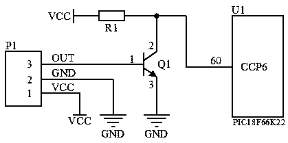
[0015] Figure 1, Figure 2, image 3 As shown, an infrared remote control signal decoding circuit includes an infrared receiver P1, and is characterized in that it also includes a single-chip microcomputer U1, a transistor Q1 and a resistor R1.

[0016] The base pin 1 of the transistor Q1 is connected to the output pin 3 of the infrared receiver P1, the collector pin 2 of the transistor Q1 is connected to one end of the resistor R1 and pin 60 of the capture interrupt port of the microcontroller U1, and the emitter pin 3 of the transistor Q1 is grounded , the other end of the resistor R1 is connected to the power supply VCC, pin 1 of the infrared receiver P1 is connected to the power supply VCC, and pin 2 is grounded.

[0017] The model of microcontroller U1 is: PIC18F66K22.

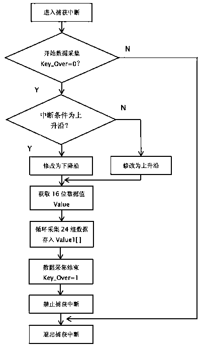
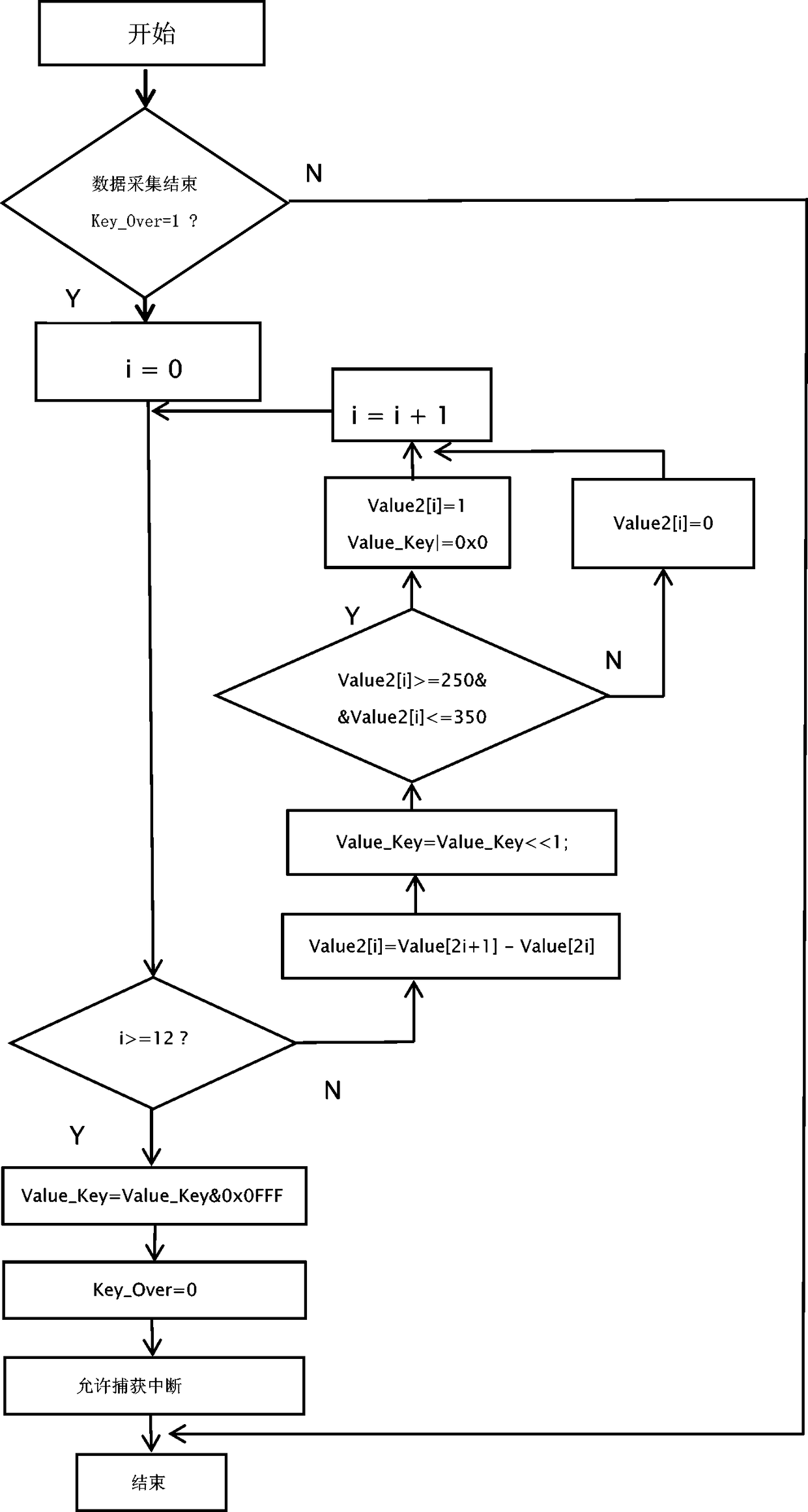
[0018] An infrared remote control signal decoding circuit and its implementation method, the steps are as follows: after the infrared receiver P1 receives the infrared signal, it outputs 12 pulse sequenc...


PUM


Abstract

The invention relates to a decoding circuit of an infrared remote control signal and an implementation method thereof. The implementation method includes the following steps that pulse signals are output through three-pin after an infrared receiver P1 receives infrared signals; the pulse signals pass an audion Q1 and a resistor R1 and are amplified; finally, the pulse signals are input to a capture interrupt end port of a single chip microcomputer U1, and the single chip microcomputer U1 enters into the capture interrupt after receiving the pulse signals; and interrupt conditions are constantly modified in a capture interrupt program, that is, the width of each pulse of a pulse sequence is calculated by using a rising edge interrupt and a falling edge interrupt, a key value corresponding to each key is calculated according to measurement data of the length of a pulse width, the corresponding key values are then determined, and the purpose of remote control signal decoding is achieved.The decoding circuit replaces a special decoding chip, not only is the cost reduced, but also the stability of the performance is improved, and more complex remote control is realized.

Description

technical field [0001] The invention relates to a decoding circuit of an infrared remote control signal and a realization method thereof, and relates to a decoding circuit of an infrared remote control signal based on a single-chip microcomputer and a method for realizing remote control decoding. Background technique [0002] With the popularization of household appliances and audition products, infrared remote controllers have been widely used in various types of household appliances, financial and commercial facilities, providing users with convenient control methods. However, for the reception and identification of infrared remote control signals, the decoding chip matched with the encoding and debugging chip is often used. More complex infrared signals need to use a dedicated remote control decoding chip. this way [0003] This method is not only expensive, but also has great limitations. Contents of the invention [0004] In view of the deficiencies in the prior art...

Claims


Application Information

Patent Timeline
IPC IPC(8): G08C23/04
CPCG08C23/04
Inventor 王伟张志明
Owner ZHONGHUAN TIG
Features
  • R&D
  • Intellectual Property
  • Life Sciences
  • Materials
  • Tech Scout
  • Unparalleled Data Quality
  • Higher Quality Content
  • 60% Fewer Hallucinations
Learn More