A Dielectric Resonant Antenna with Tunable Band Traps

A technology of dielectric resonant antenna and dielectric resonator, which is applied in the direction of antenna, antenna grounding device, antenna grounding switch structure connection, etc., can solve problems such as inapplicability

Active Publication Date: 2019-07-09
黑龙江省工研院资产经营管理有限公司
View PDF3 Cites 0 Cited by
  • Summary
  • Abstract
  • Description
  • Claims
  • Application Information

AI Technical Summary

Problems solved by technology

However, the radiator of the dielectric resonant antenna is a dielectric similar to ceramic materials, and the technical means of etching gaps like metal radiation patches is not applicable. At present, there are almost no dielectric resonant antennas with adjustable band gap published.

Method used


Image

  • A Dielectric Resonant Antenna with Tunable Band Traps
  • A Dielectric Resonant Antenna with Tunable Band Traps
  • A Dielectric Resonant Antenna with Tunable Band Traps

Examples


Embodiment Construction

[0018] The technical solutions in the embodiments of the present invention will be clearly and completely described below in conjunction with the drawings in the embodiments of the present invention.

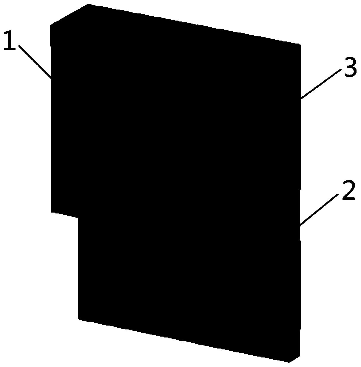
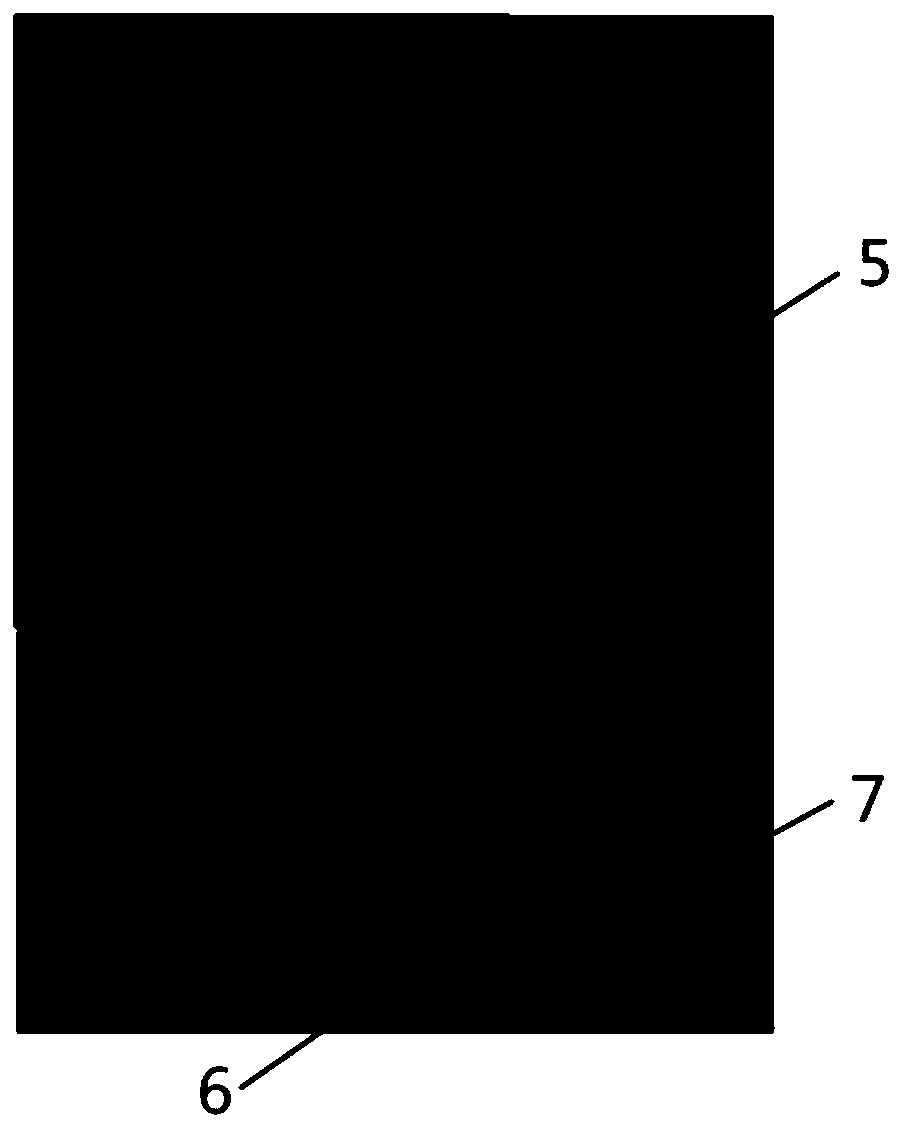
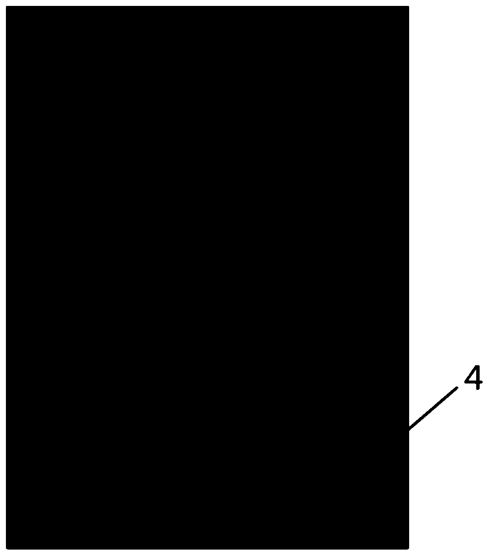
[0019] see Figure 1-7 Describe this embodiment, a dielectric resonant antenna with adjustable band trapping characteristics, which includes a dielectric resonator 1, a stepped impedance microstrip line 2, a dielectric substrate 3, a defective floor 4, a first radio frequency switch 5, and a second radio frequency switch 6 and a third radio frequency switch 7, the dielectric resonator 1 is located on the front of the dielectric substrate 3, the dielectric resonator 1 is in contact with the stepped impedance microstrip line 2, and the stepped impedance microstrip line 2 includes a low The impedance part and the high impedance part with a rectangular ring gap, the stepped impedance microstrip line 2 is located on the front of the dielectric substrate 3 and not on the center line o...


PUM


Abstract

The invention provides a dielectric resonant antenna with an adjustable band trap characteristic, belonging to the field of radio communication, and particularly relates to a dielectric resonant antenna with an adjustable band trap characteristic. The problem that at present band trap-adjustable dielectric resonant antennas hardly eixst is solved. The dielectric resonant antenna comprises a dielectric resonator, a step impedance microstrip line, a dielectric substrate, a defective floor, a first radio frequency switch, a second radio frequency switch and a third radio frequency switch, and ismainly used in the field of radio communication.

Description

technical field [0001] The invention belongs to the field of radio communication, in particular to a dielectric resonant antenna with adjustable band trap characteristics. Background technique [0002] In 1983, Professor Long of the University of Houston proposed the dielectric resonant antenna for the first time. Dielectric resonant antennas have a series of advantages such as miniaturization, light weight, high radiation efficiency, flexible design, and easy excitation, and have been continuously researched in the past thirty years. The research results mainly focus on the study of broadened frequency band, circular polarization, high-order mode, high gain, high frequency band and array. The existing research results show that the dielectric resonant antenna has the potential of ultra-wideband application. Wideband antennas with notched characteristics can avoid electromagnetic interference from relatively narrowband systems. In order to coexist with traditional narrowb...

Claims


Application Information

Patent Timeline
Patent Type & Authority Patents(China)
IPC IPC(8): H01Q1/50H01Q1/48H01Q5/10H01Q5/28H01Q5/335
CPCH01Q1/48H01Q1/50H01Q5/10H01Q5/28H01Q5/335
Inventor 刘北佳邱景辉矫健林林澍
Owner 黑龙江省工研院资产经营管理有限公司
Why Eureka
Try Eureka