Sewage drainage mechanism of fishpond cleaning system

A technology of sewage discharge mechanism and fish pond, applied in fish farming, application, animal husbandry, etc., can solve the problems of low work efficiency, large water storage capacity, time-consuming and labor-consuming, etc., achieve good effect, fast sewage discharge, avoid The effect of opening the angle too large

Inactive Publication Date: 2018-12-18
合肥亿翔智能制造有限公司
9 Cites 0 Cited by

AI-Extracted Technical Summary

Problems solved by technology

[0003] However, due to the large area of ​​the fish pond, the large amount of water storage, and the variety of fish raised in the pond, the cleaning of the fish pond is ...

Abstract

The invention discloses a sewage drainage mechanism of a fishpond cleaning system. The sewage drainage mechanism comprises a fishpond, a pond bottom of the fishpond is in a funnel shape, a sewage drainage port is formed in the pond bottom of the fishpond, a sewage drainage valve is installed on the sewage drainage port, and a driving mechanism is installed on the sewage drainage valve; the sewagedrainage valve comprises a valve body and a valve lid; the valve lid is rotatably fixed to the valve body; the valve body is further provided with a limiting block to control the maximal opening angleof the valve lid to be smaller than 90 degrees. According to the sewage drainage mechanism, the sewage drainage valve is arranged at the funnel-shaped pond bottom and communicated with the outside through a sewage drainage pipeline, so that the sewage drainage speed is high and the sewage drainage effect is good; besides, through the cooperation of an air cylinder/oil cylinder, a pulley and a traction rope, the valve lid of the sewage drainage valve is opened and closed conveniently; through limiting of a limiting plate, the opening angle of the valve lid is smaller than 90 degrees to avoid the situation that the opening angle is too large and a user cannot close the valve lid by himself/herself.

Application Domain

Pisciculture and aquaria

Technology Topic

EngineeringSewage +3

Image

  • Sewage drainage mechanism of fishpond cleaning system
  • Sewage drainage mechanism of fishpond cleaning system
  • Sewage drainage mechanism of fishpond cleaning system

Examples

  • Experimental program(1)

Example Embodiment

[0013] In order to make the objectives, technical solutions, and advantages of the embodiments of the present invention clearer, the technical solutions in the embodiments of the present invention will be described clearly and completely in conjunction with the accompanying drawings in the embodiments of the present invention. Obviously, the described embodiments It is a part of the embodiments of the present invention, not all the embodiments. Based on the embodiments of the present invention, all other embodiments obtained by those of ordinary skill in the art without creative work shall fall within the protection scope of the present invention.
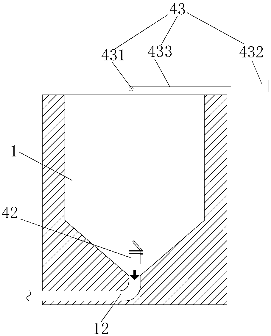
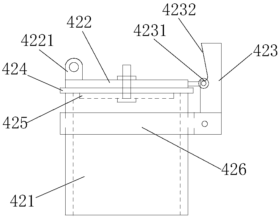
[0014] A sewage discharge mechanism of a fish pond cleaning system includes a fish pond 1. The bottom of the fish pond 1 is funnel-shaped, and the bottom of the fish pond 1 is provided with a sewage outlet 12; and a sewage valve is fixed at the sewage outlet 12 42; The drain valve 42 is opened and closed by the driving mechanism 43.
[0015] The drain valve 42 includes a valve body 421, a valve cover 422, and a driving mechanism 43; the valve cover 422 is rotatably fixed on the valve body 421; the valve body 421 is also provided with a limit block 423, which is vertically fixed on the valve body 421 A plate structure on the outer wall; the limit block 423 is provided with a step 4231 facing the valve body 421 side, and the valve cover 422 is fixed on the step 4231 by rotation; the side of the plate body above the step 4231 is a slope 4232, the slope 4232 and the step The included angle of 4231 is less than 90° to control the maximum opening angle of valve cover 422 to be less than 90°; generally 75° to ensure that the valve cover can be normally closed under its own weight after the cleaning work is completed; limit block 423 can pass It is fixed on the valve body 421 by welding, or it can be welded on the clamp 426, which is fixed on the valve body 421, which is convenient for disassembly, cleaning and maintenance.
[0016] The driving mechanism 43 includes a pulley 431 fixed above the fish pond 1, a driving part 432, and a pulling wire 433; the pulling wire 433 is generally a steel wire rope; on the side opposite to the hinge point of the valve cover 422, a lifting lug 4221 is provided; one end of the pulling wire 433 It is fixed to the lifting lug 4221, and one end bypasses the pulley 431 and is fixed to the output end of the driving part 432 (air cylinder or oil cylinder).
[0017] The lower surface of the valve cover 422 is also fixed with a sealing gasket 424, and a stainless steel gasket 425 is also fixed on the lower surface of the sealing gasket 424. The stainless steel gasket 425, the sealing gasket 424, and the valve cover 422 are fixed as a whole by screws.
[0018] It should be noted that in this article, if there are relational terms such as first and second, etc., it is only used to distinguish one entity or operation from another entity or operation, and does not necessarily require or imply these entities or operations There is any such actual relationship or order between. Moreover, the terms "include", "include" or any other variants thereof are intended to cover non-exclusive inclusion, so that a process, method, article, or device that includes a series of elements includes not only those elements, but also includes Other elements of, or also include elements inherent to this process, method, article or equipment. If there are no more restrictions, the element defined by the sentence "including a..." does not exclude the existence of other same elements in the process, method, article, or equipment that includes the element.
[0019] The above embodiments are only used to illustrate the technical solutions of the present invention, not to limit them; although the present invention has been described in detail with reference to the foregoing embodiments, a person of ordinary skill in the art should understand that: The recorded technical solutions are modified, or some of the technical features are equivalently replaced; these modifications or replacements do not cause the essence of the corresponding technical solutions to deviate from the spirit and scope of the technical solutions of the embodiments of the present invention.

PUM

no PUM

Description & Claims & Application Information

We can also present the details of the Description, Claims and Application information to help users get a comprehensive understanding of the technical details of the patent, such as background art, summary of invention, brief description of drawings, description of embodiments, and other original content. On the other hand, users can also determine the specific scope of protection of the technology through the list of claims; as well as understand the changes in the life cycle of the technology with the presentation of the patent timeline. Login to view more.

Similar technology patents

Moisture-proof device for motor

InactiveUS20050012416A1increase in production capacitygood effect
Owner:DELTA ELECTRONICS INC

Detecting system and method for partial discharge detecting sensor of GIS (gas insulated switchgear)

ActiveCN103336259AThe result is intuitive and accurategood effect
Owner:STATE GRID CORP OF CHINA +2

Pulsed plasma thruster with ceramic air spout electrode

InactiveCN101260873Agood effectSignificant increase in thrust
Owner:SHANGHAI JIAO TONG UNIV

Classification and recommendation of technical efficacy words

  • good effect
Why Eureka
Try Eureka