Pressing type bean pulp smashing device

A crushing device and compacting device technology, which is applied in the direction of grain processing, etc., can solve the problems of soybean meal sticking on the crushing plate body, affecting work, affecting the quality and work efficiency of soybean meal crushing, etc., achieving ingenious structural design, reasonable structure, Effects that add mass and effect

Pending Publication Date: 2018-12-18
JIANGSU JINMAN SCI & TECH
0 Cites 0 Cited by

AI-Extracted Technical Summary

Problems solved by technology

[0002] In the production process of the existing formaldehyde-free soybean meal gel, it is necessary to crush the soybean meal into a soybean meal granular structure with a smaller particle size; then it is filtered and then used for the production of the soybean meal gel; The soybean meal is crushed by means of crushing and pressing; but most of the existing crushing d...

Method used

In the present invention, after the soybean meal raw material enters from the upper feed port of the crushing box, the main shaft is driven by the opening of the crushing motor to rotate, and the main shaft drives the square rods on both sides to rotate, and the square rods on both sides are respectively installed with rollers by the pressing device Shaft and dial, and the crushing roller is installed on the roller shaft, and the driving rod is installed on the dial; the pressing device is composed of a sleeve, a sleeve rod and a compression spring, so that the roller shaft and the dial can be aligned with the square rod above. It is connected as a whole to make it rotate together, and can press the crushing roller and the lever to press on the screen; when the crushing roller rotates, the crushing sawtooth on the surface of the crushing roller crushes the soybean meal raw material put in processing; and...

Abstract

The invention discloses a pressing type bean pulp smashing device which comprises a smashing tank. A screen is arranged in the smashing tank; a stock bin is arranged at the area under the screen; a bearing seat is further arranged in the middle of the screen; a smashing motor is further arranged above the smashing tank; a main shaft is arranged on a motor rod of the smashing motor, stretches intothe tank from the upper part of the smashing tank, and is arranged on the bearing seat of the screen; and square rods horizontally stretching out from two sides are further arranged on the main shaft.According to the device, after smashing through a smashing and pressing roller every time, a driving lever closely follow to plough again, so that the device is ingenious in overall structure designand clear in principle; and one same smashing motor is utilized for installing a smashing mechanism and a ploughing mechanism, so that the device is reasonable in structure and convenient to use.

Application Domain

Technology Topic

Image

  • Pressing type bean pulp smashing device

Examples

  • Experimental program(1)

Example Embodiment

[0011] The present invention will be further clarified below with reference to the drawings and specific embodiments. This embodiment is implemented on the premise of the technical solution of the present invention. It should be understood that these embodiments are only used to illustrate the present invention and not to limit the scope of the present invention.
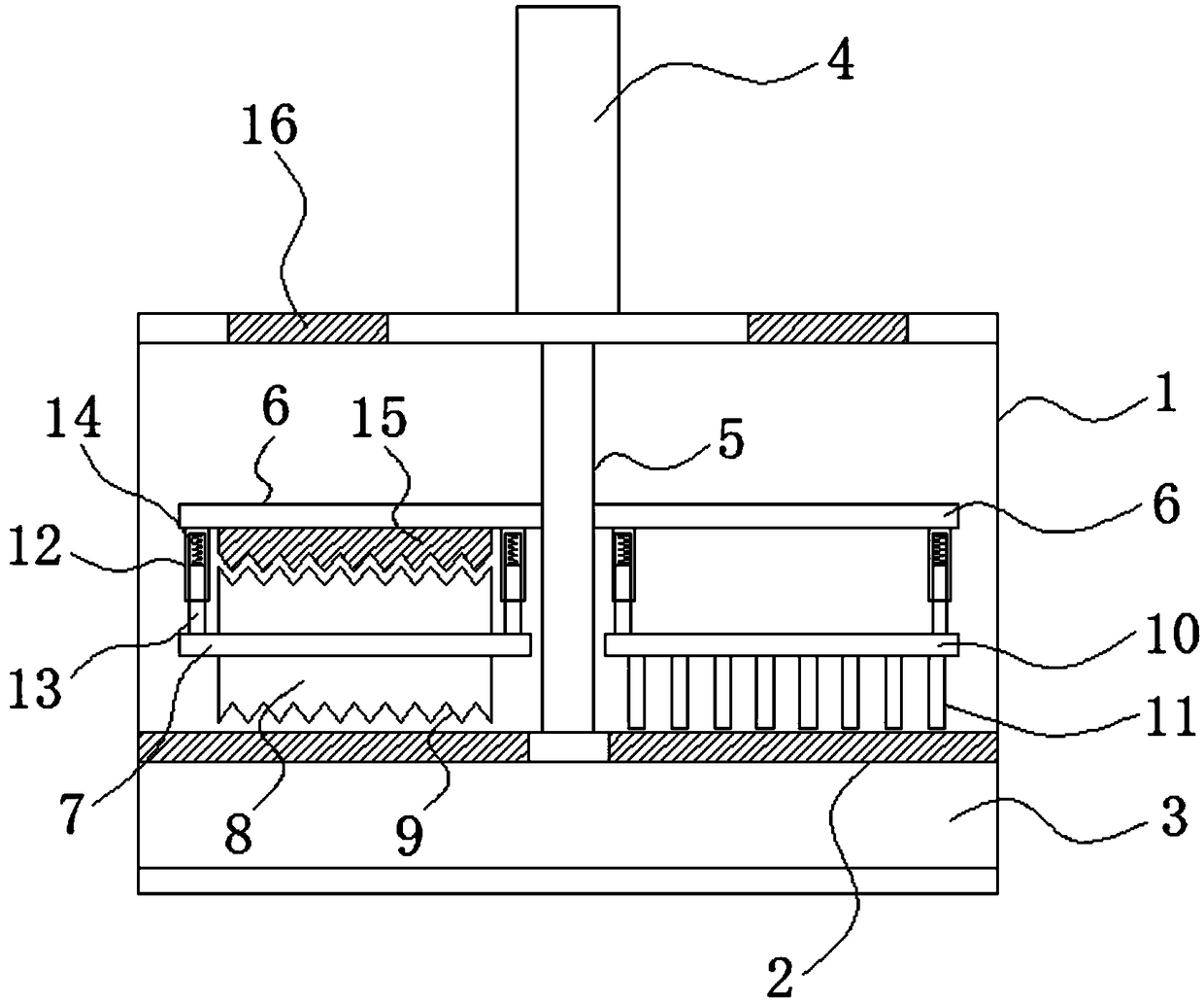
[0012] Such as figure 1 As shown, a compression type soybean meal crushing device includes a crushing box 1; a screen 2 is installed in the crushing box 1; the area below the screen 2 is set as a silo 3; and the middle position of the screen 2 is also set There is a bearing seat; above the crushing box 1 is also installed a crushing motor 4; the motor rod of the crushing motor 4 is installed with a spindle 5, the spindle 5 extends from the crushing box 1 into the box and installed in the screen On the bearing seat 3 of the net 2; and the main shaft 5 is also installed with a square rod 6 extending laterally to both sides; one of the rods 6 is installed with a horizontally placed roller shaft through a downward vertical pressing device 7; And the roller shaft 7 is installed with a horizontally placed crushing roller 8, the crushing roller 8 is pressed against the screen 2 under the action of the pressing device, and the crushing roller 8 is also provided with crushing Press saw teeth 9; and the other side rod 6 is also installed with a horizontally arranged dial plate 10 through a downward vertical pressing device; and the lower end of the dial plate 10 is installed with a vertically downwardly arranged dial rod 11 The lever 11 is pressed tightly on the screen 2 under the action of the pressing device.
[0013] Each of the square rods 6 is provided with a pressing device at both ends; the pressing device includes a sleeve 12 installed on the lower end surface of the square rod 6, and the sleeve 12 is arranged vertically downward and in the A pressure rod 13 is installed in the sleeve 12; and the pressure rod 13 is correspondingly installed on the roller shaft 7 and the shift plate 10; and a compression spring 14 is installed between the upper end of the pressure rod 13 and the upper end of the sleeve 12.
[0014] The extending direction of the crushing and pressing serrations 9 is set to be perpendicular to the axis of the roller shaft 7; and the lower end surface of the square rod 6 for installing the roller shaft 7 is also provided with a serration bar 15; The saw teeth on the pressing saw teeth 9 correspond to each other, and the saw teeth of the saw tooth bar 15 are clamped into the crushing saw teeth 9 from above; there are a total of eight shift levers 11 installed vertically downward on the shift plate 10; and The bottom of the rod 11 is provided with an arc structure; the upper end of the crushing box 1 is provided with a feed port 16.
[0015] In the present invention, the soybean meal raw material enters from the upper feeding port of the crushing box, and the main shaft is driven to rotate by the opening of the crushing motor, and the main shaft drives the square rods on both sides to rotate. The square rods on both sides are respectively installed with rollers and dials through a pressing device. Plate, and a crushing roller is installed on the roller shaft, and a dial rod is installed on the dial plate; the compression device is composed of a sleeve, a sleeve rod and a compression spring, so that the roller shaft and the dial plate can be connected with the square rod above. Make it rotate together, and can press the crushing roller and the lever to press on the screen; when the crushing roller rotates, the crushing serrations on the surface of the crushing roller will crush the put soybean meal raw material; and The shift lever that rotates along with it plows the crushed soybean meal in front. This setting is beneficial to the next crushing of the soybean meal raw material after plowing, and prevents the soybean meal from sticking to the screen; on the other hand, the soybean meal after plowing is beneficial The raw materials that meet the conditions of the screen are sieved from the screen; and under the action of the pressing device, the crushing roller and the lever will be tightly pressed on the screen to increase the quality and effect of the crushing; this device crushes the crushing roller every time After that, the shift lever will re-plow immediately. The overall structure is ingeniously designed and the principle is clear. The same crushing motor is used to install the crushing mechanism and the plowing mechanism. The structure is reasonable and easy to use.
[0016] The above specific implementation is only a preferred embodiment of the present invention, and is not used to limit the implementation of the present invention and the scope of the claims. All equivalent changes and modifications made according to the content described in the patent protection scope of the present invention are all It should be included in the scope of the patent application of the present invention.

PUM

no PUM

Description & Claims & Application Information

We can also present the details of the Description, Claims and Application information to help users get a comprehensive understanding of the technical details of the patent, such as background art, summary of invention, brief description of drawings, description of embodiments, and other original content. On the other hand, users can also determine the specific scope of protection of the technology through the list of claims; as well as understand the changes in the life cycle of the technology with the presentation of the patent timeline. Login to view more.

Similar technology patents

Product surface ironing equipment for silk product processing and production

PendingCN114737344AImprove quality and performanceIncreased flattening effectFabric steaming/decatisingSilk clothProduct processing
Owner:HUZHOU SIYI SILK

Classification and recommendation of technical efficacy words

  • Improve quality and performance
  • Ingenious structural design

Quenching process of H13 steel aluminum alloy die-casting die

InactiveCN106755880AThe quenching process is simpleImprove quality and performanceFurnace typesHeat treatment furnacesQuenchingStress relief
Owner:巴南区伟鹏机械加工厂

Automatically continuous carbon fiber winding device

ActiveCN104261202AContinuous winding and roll changingIngenious structural designFilament handlingAutomatic controlElectric machinery
Owner:ZHEJIANG JINGGONG SCI & TECH

Full-automatic assembly machine for bottom shell component of hanging headphone

ActiveCN107770715AReduce collection and transportation costsIngenious structural designMicrophonesLoudspeakersLight barrierHeadphones
Owner:CHONGQING TECH & BUSINESS UNIV
Why Eureka
Try Eureka