Eureka AIR delivers breakthrough ideas for toughest innovation challenges, trusted by R&D personnel around the world.

Shaft tube chamfering device for transmission shaft machining

A technology of chamfering device and drive shaft, which is applied in metal processing and other directions, can solve the problems of low loading and unloading efficiency, affecting the efficiency of shaft tube processing, and low chamfering efficiency, and achieves the effect of facilitating assembly and improving work efficiency

Inactive Publication Date: 2018-12-18
JIASHAN RUIYI ELECTRONICS TECH
View PDF0 Cites 2 Cited by
  • Summary
  • Abstract
  • Description
  • Claims
  • Application Information

AI Technical Summary

Problems solved by technology

[0003] The existing shaft tube chamfering device still has certain defects in use. Although the existing shaft tube chamfering device can chamfer the shaft tube, there is a problem of low loading and unloading efficiency during the chamfering process, which affects The efficiency of shaft tube processing is reduced, and the existing chamfering devices are generally single-sided chamfering, which has low chamfering efficiency

Method used


Image

  • Shaft tube chamfering device for transmission shaft machining
  • Shaft tube chamfering device for transmission shaft machining
  • Shaft tube chamfering device for transmission shaft machining

Examples


Embodiment 1

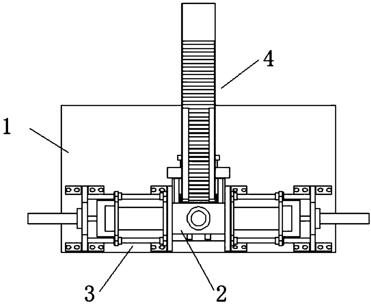
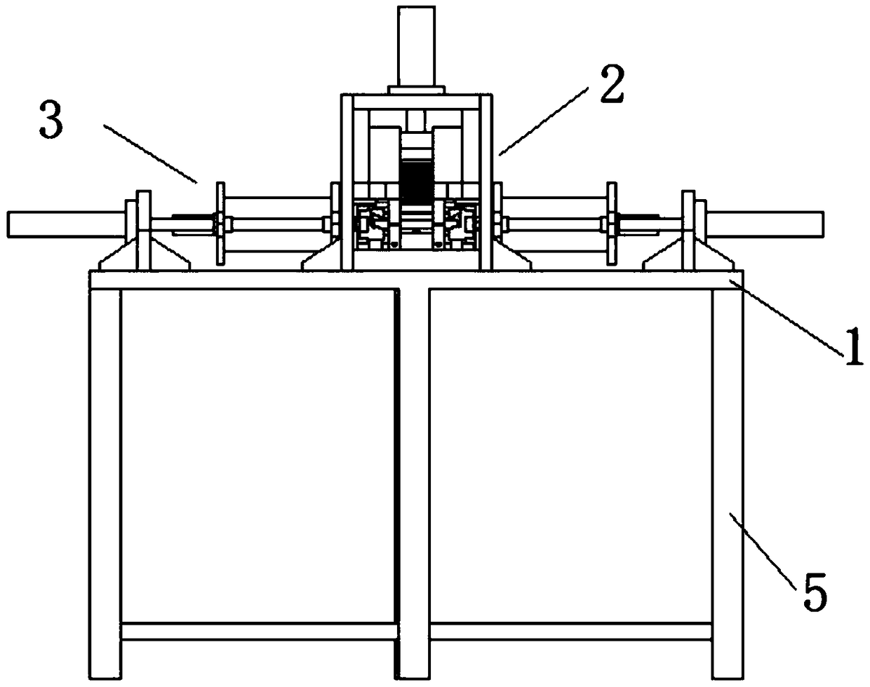
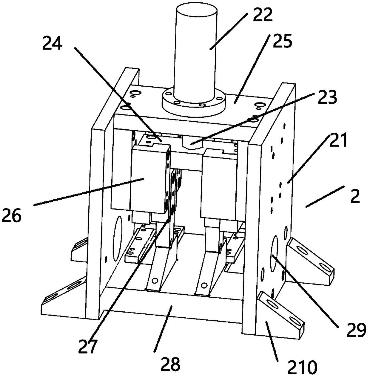
[0022] Such as figure 1As shown, a shaft tube chamfering device for transmission shaft processing proposed by the present invention includes a workbench 1 welded on the top of the frame 5, a fixing mechanism 2 fixed in the middle of the workbench 1, a chamfering mechanism 3 and The feeding mechanism 4 and the two chamfering mechanisms 3 are respectively arranged on both sides of the fixing mechanism 2, the feeding mechanism 4 is installed behind the fixing mechanism 2, and the chamfering mechanism 3 and the feeding mechanism 4 are all fixed on the workbench 1, and the fixing mechanism 2 is used to engage and fix the shaft tube, two chamfering mechanisms 3 respectively chamfer the left and right ends of the shaft tube, and the feeding mechanism 4 is used for automatic feeding; the fixing mechanism 2 includes two first fixing plates 21 arranged in parallel And the pressure plate 27, the first fixing plate 21 is vertically fixed on the workbench 1 through the first mounting foot ...

Embodiment 2

[0024] In addition, please continue to refer to Figure 2-5 , different from the above-mentioned embodiment, the first moving plate 47 both sidewalls are provided with a limit plate 48, the limit plate 48 is a rectangular plate, the limit plate 48 is fixed on the fixed seat 28 by bolts, so that the limit plate 48 can be used 48 to engage both sides of the first shifting plate 47 to ensure that the first shifting plate 47 can move according to a fixed track. The first shifting plate 47 is a square plank, the second shifting plate 49 is a triangular plank, and the second shifting plate 49 is concave at the top. A groove with an arc-shaped structure is provided, and the groove is located directly below the rubber stopper 411. The first moving plate 47 and the second moving plate 49 are connected by bolts, and a torsion spring is sleeved outside the bolt, and the two ends of the torsion spring Connect the first shifting plate 47 and the second shifting plate 49 respectively, so th...


PUM


Abstract

The invention discloses a shaft tube chamfering device for transmission shaft machining, and relates to the technical field of transmission shaft machining application. The device comprises a worktable, a fixing mechanism, a chamfering mechanism, a feeding mechanism, a frame, a first fixed plate, a first cylinder, a first extension rod, a mounting plate, a second fixed plate, a clamping plate, a pressing plate, a fixed base, a through hole, a first fixed foot, a motor, a drill bit, a third fixed plate, a second fixed foot, a second cylinder, a second extension rod, a connecting rod, a fixed frame, a mounting frame, a first transportation plate, a second transportation plate, a support frame, a fourth fixed plate, a third cylinder, a connecting plate, a first movable plate, a limiting plate, a second movable plate, a clamping plate and a rubber baffle plate. The device has the following beneficial effects: two chamfering mechanisms are symmetrically arranged on two sides of the fixing mechanism; the chamfering mechanisms, symmetrically arranged, are used for synchronously chamfering the left and right ends of shaft tubes; the edges of the shaft tubes are cut as a certain inclined surfaces; and meanwhile, the two ends of the shaft tubes are chamfered, so that the chamfering efficiency is effectively improved.

Description

technical field [0001] The invention relates to the technical field of transmission shaft processing applications, in particular to a shaft tube chamfering device for transmission shaft processing. Background technique [0002] The transmission shaft is a rotating body with high speed and few bearings, so its dynamic balance is very important. Generally, the transmission shaft must undergo a dynamic balance test before leaving the factory and be adjusted on a balancing machine. For a car with a front-engine rear-wheel drive, it is the shaft that transmits the rotation of the transmission to the final drive. It can be several sections, and the sections can be connected by universal joints. When the transmission shaft is being processed, a chamfering device is required to chamfer the shaft tube, and cut the corners of the shaft tube into a certain slope, which is convenient for the assembly of the shaft tube. [0003] The existing shaft tube chamfering device still has certa...

Claims


Application Information

Patent Timeline
IPC IPC(8): B23D79/00B23Q7/00
CPCB23D79/00B23Q7/00
Inventor 钱明奎
Owner JIASHAN RUIYI ELECTRONICS TECH
Why Eureka
Eureka Blog
Learn More