Die-cutting machine allowing position of die-cutting tool to be conveniently adjusted

A die-cutting knife and die-cutting machine technology, which is applied in metal processing and other directions, can solve the problems of cumbersome way of adjusting the position of the die-cutting knife, reducing the processing efficiency of the product, and prolonging the time of adjusting the position of the die-cutting knife. The effect of improving machining efficiency and shortening adjustment time

Inactive Publication Date: 2018-12-18
石纪康
View PDF0 Cites 3 Cited by
  • Summary
  • Abstract
  • Description
  • Claims
  • Application Information

AI Technical Summary

Problems solved by technology

[0005] Aiming at the deficiencies in the prior art, the present invention provides a die-cutting machine that can easily adjust the position of the die-cutting knife, which solves the problem that the positions of the die-cutting knives of some current die-cutting machines are mostly fixed settings, and some die-cutting machines also have to adjust the position of the die-cutting machine. The way of adjusting the position of the cutter is too cumbersome, which not only prolongs the time for adjusting the position of the die cutter, but also reduces the problem of product processing efficiency

Method used


Image

  • Die-cutting machine allowing position of die-cutting tool to be conveniently adjusted
  • Die-cutting machine allowing position of die-cutting tool to be conveniently adjusted
  • Die-cutting machine allowing position of die-cutting tool to be conveniently adjusted

Examples


Embodiment Construction

[0022] The following will clearly and completely describe the technical solutions in the embodiments of the present invention with reference to the accompanying drawings in the embodiments of the present invention. Obviously, the described embodiments are only some, not all, embodiments of the present invention. Based on the embodiments of the present invention, all other embodiments obtained by persons of ordinary skill in the art without making creative efforts belong to the protection scope of the present invention.

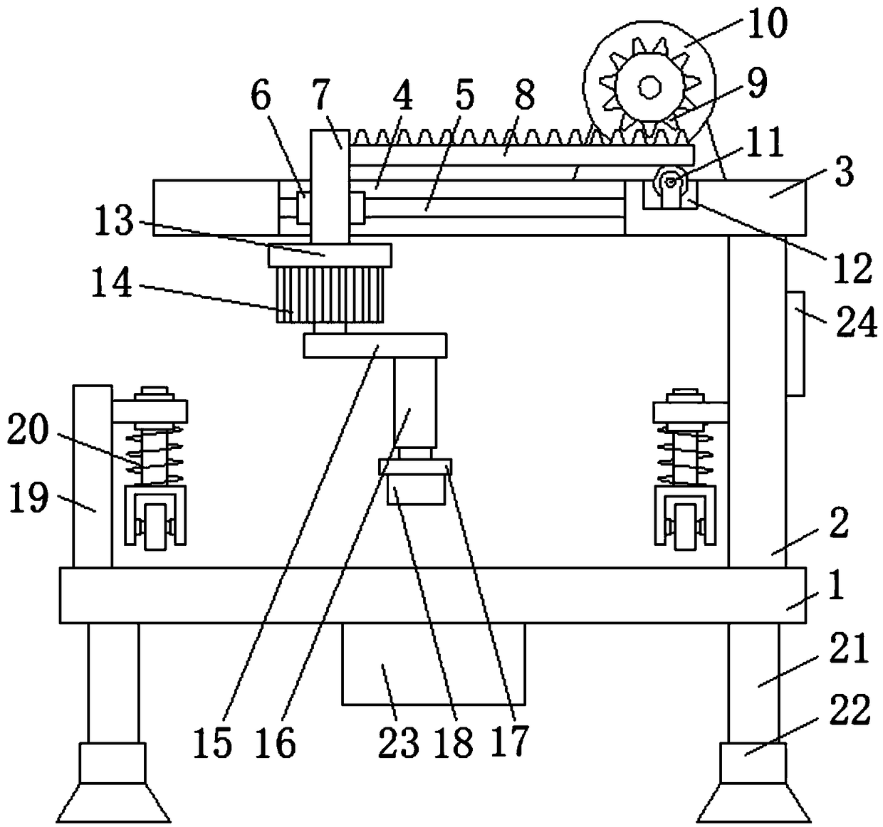
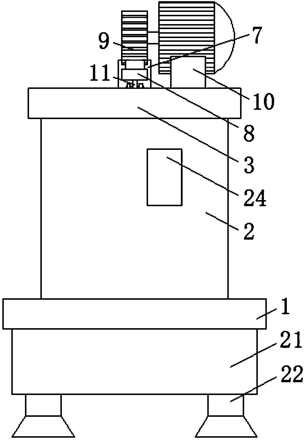
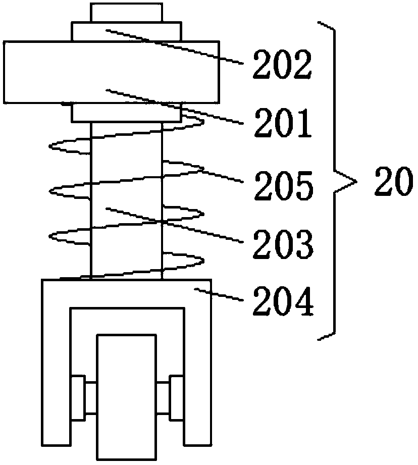
[0023] Such as Figure 1-3 As shown, the present invention provides a technical solution: a die-cutting machine for conveniently adjusting the position of the die-cutter, including a bottom plate 1, by setting the bottom plate 1, the die-cutter body 18 can be better fixed, and at the same time it can be better The printed matter is placed, the left and right sides of the lower surface of the bottom plate 1 are fixedly connected with support blocks 21, the widt...


PUM


Abstract

The invention discloses a die-cutting machine allowing the position of a die-cutting tool to be conveniently adjusted. The die-cutting machine comprises a bottom plate; the upper surface of the bottomplate is fixedly connected with the lower surface of a supporting plate through a first fixing plate; a through hole is formed in the upper surface of the supporting plate; the left side face and theright side face of the inner wall of the through hole are fixedly connected through a first sliding rod; a first sliding sleeve is connected to the surface of the first sliding rod in a sleeving mode; the first sliding sleeve is clamped to the right side face of a first connection rod; the right side face of the first connection rod is fixedly connected with the left end of a toothed bar which isengaged with a gear; and the gear is fixedly connected to the surface of a first motor output shaft. According to the die-cutting machine allowing the position of the die-cutting tool to be conveniently adjusted, through arrangement of a first motor, the toothed bar, the first connection rod, a second motor, a second connection rod and an electric push rod, the position of a die-cutting tool bodycan be more conveniently adjusted through operation of the first motor and the second motor, the time for adjusting the die-cutting tool body is shortened, and thus the product machining efficiency is improved.

Description

technical field [0001] The invention relates to the technical field of die-cutting equipment, in particular to a die-cutting machine for conveniently adjusting the position of a die-cutting knife. Background technique [0002] Die-cutting machine is also called beer machine, cutting machine and CNC punching machine, mainly used for die-cutting, indentation and bronzing of some non-metallic materials, self-adhesive, EVA, double-sided tape, electronic and mobile phone rubber pads, etc. Operation, lamination and automatic waste discharge, the die-cutting machine uses steel knives, metal molds and steel wires to apply a certain pressure through the embossing plate to roll and cut the printed matter or cardboard into a certain shape. [0003] The position of the die-cutting knife of some current die-cutting machines is mostly fixed, and some die-cutting machines adjust the position of the die-cutting knife too cumbersomely, which not only prolongs the time for adjusting the posit...

Claims


Application Information

Patent Timeline
IPC IPC(8): B26F1/38B26D7/26B26D7/02
CPCB26F1/38B26D7/025B26D7/2628
Inventor 石纪康
Owner 石纪康
Why Eureka
Try Eureka